FIRST Robotics
9/2019 - 6/2023
Numerous contributions to the competition robots, from kinematics to award-winning computer vision
Written by: Violet Monserate

What is FIRST Robotics Competition?
The blurb from the homepage of FIRST Robotics Competition (FRC) (For Inspiration and Recognition of Science and Technology) explains the competition well:
“Teams of high school students design, program, and build industrial-sized robots to play an action-packed game, released in January. They compete on a themed field as part of a three-team alliance.”
As a member of two different teams over the years, I have observed that despite differences in team culture and identity, there’s a shared spirit of engineering, even in the face of complex design challenges, and an enthusiasm for elevating the knowledge of all members. I have learned a great deal over the years in FRC, and I hope to illustrate that growth and learning in this blog post.
Freshman Year (2020 Season @ Skunk Works Robotics)
Before joining Skunk Works Robotics, I was familiar with Java, but never fully understood its Object-Oriented foundations. My first year was when I learned about the true importance of proper software architecture and the value of modular components that abstractly represent concrete subsystems on the robot, thereby maximizing concurrent development.
Despite the season being cut short due to the COVID-19 pandemic, I was able to write code for the robot that year, specifically to autonomously rotate the control panel to the right color or the correct number of rotations (see the 2020 FRC Game Animation for more information). The business logic was well unit-tested using JUnit and also with systems testing on the actual competition robot on the practice field. I also gained experience utilizing constructs like enum and class, and really started to grasp what OOP is all about.
In terms of robotics engineering, I also learned how to utilize and tune PID controllers for the flywheel-based shooter and observe how a Pure Pursuit path planner works for the autonomous portion of the game.
I will not say that the process was easy, however. Numerous challenges got in the way. For one, I had jumped into the deep end in terms of Java Development, with only a slight knowledge of OOP (especially tools like interface and extends). Developing software for a vital part of our robot was truly a trial by fire, and in the end, I made it through and truly developed my skills along the way. While the code was never truly “battle-tested” in the heat of competition (again, due to the COVID-19 pandemic)
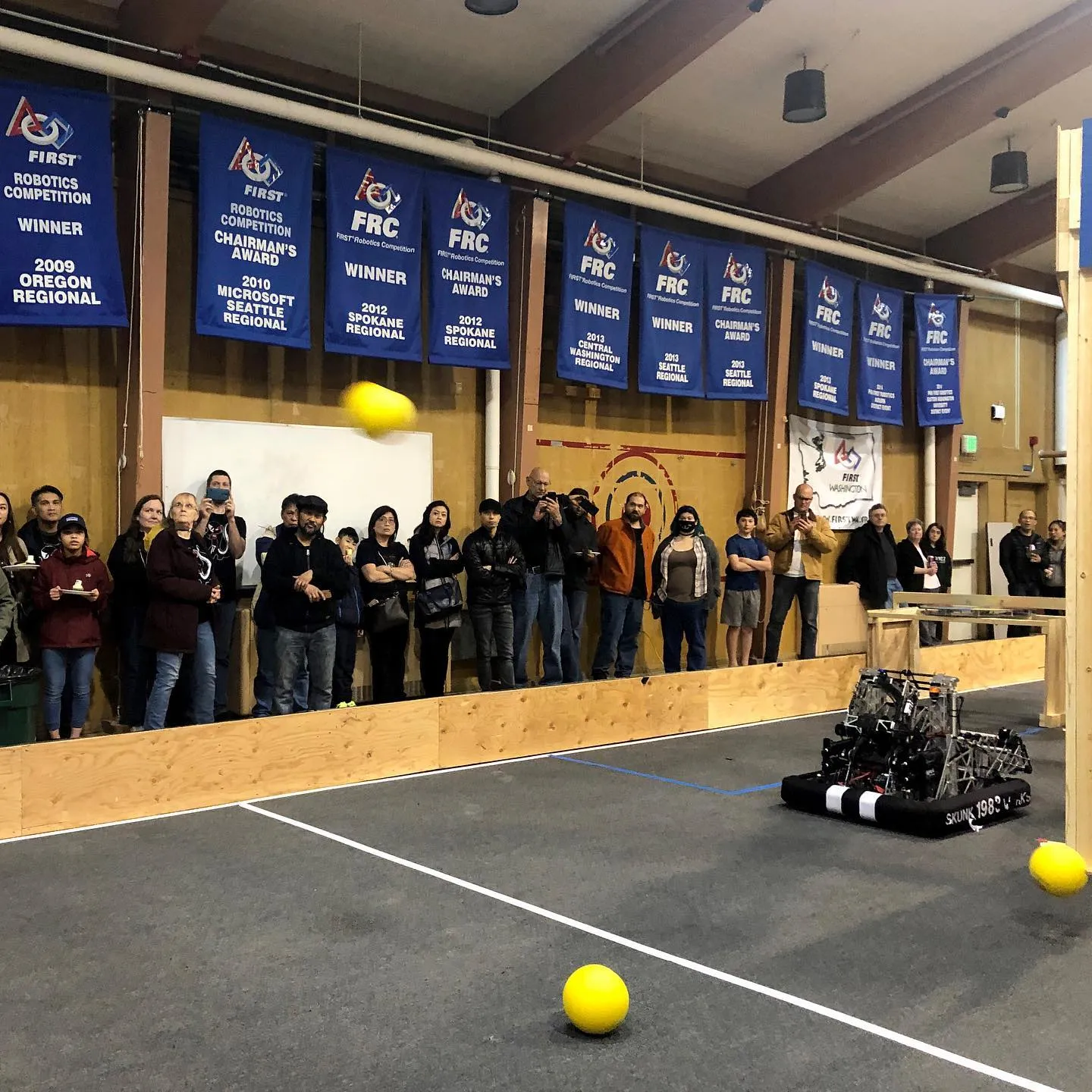 Fig 1. The competition robot at our robot reveal. We demonstrated its capabilities, including the capability to fire into the inner port from nearly anywhere on the field
Sophomore Year (2021 Season @ Skunk Works Robotics)
As social distancing restrictions began to ease, the 2021 season (a completely virtual, time-trial-based competition utilizing the same robot from the 2020 season) commenced. This year, I learned a great deal about the Pure Pursuit path planner and was able to assist with both tuning internal parameters and creating the paths that the planner would follow.
The other system I helped tune was the shooter, which involved a couple of PID controllers that helped the flywheels rotate at a consistent velocity and ensured consistent shots at the goals.
The frustration was still very real, with both sets of tuning requiring test runs after test run. There is no “scientific” way to tune either system, and they need informed guess-and-check methods. As such, meetings would sometimes last for hours with no significant progress or improvement in consistency or speed.
Nonetheless, we forged ahead, and in the end, our team was able to win our division, earning a coveted Blue Banner for our hard work.
Junior Year (2022 Season @ Phoenix Force Robotics)
During my Junior Year, I moved to a different team: Phoenix Force Robotics. I was a far more mature coder, and thus I had the opportunity to help work on the interoperability of two challenging subsystems: computer vision and the shooter.
The shooter turret would rotate up to ±360° from center, and had an adjustable hood. As such, we implemented a method to rotate the turret to a given position (and reset it whenever we reached the rotation limits), and applied Newtonian physics to calculate hood angles and flywheel velocities given a certain distance from the target at the center of the field. While this would be useful when there is a known distance from the robot to the Upper Hub, we would then only be able to use the system in this state at specific “landmarks.” Thankfully, due to the retroreflective strips on the Upper Hub and their even spacing, we could utilize the vision system to both autonomously center the turret on the Upper Hub and judge distance from the Upper Hub.
We developed the vision system during a time of computer chip shortages, and we were unable to buy an off-the-shelf solution for vision. As such, we had to develop an in-house solution for vision, utilizing off-the-shelf cameras, LED rings, and a mini computer. By running WPILibPi on the minicomputer, we can connect the main computer and the vision processing using Ethernet.
The information generated by the vision processing was the lateral distance of the robot from the Upper Hub, along with an offset of the target relative to the center of the camera, scaled from -1 to 1. The auxiliary computer would then feed into our autonomous shooting routine, which would:
- Calculate the flight path of the ball(s)
- Speed up the flywheels to a target speed
- Center the turret
- And finally, feed the balls into the shooter
This entire system required a heavy amount of system integration testing (mainly due to documented issues with the Ethernet of the radio). Still, in the end, we helped alleviate pressure on the driver and allowed them to focus on other aspects of the game, shooting wherever and whenever they had time.
Even better, due to our ingenuity in creating our vision system from what was available to us, judges graced us with an Industrial Design Award during our first competition (which I will never live down!)
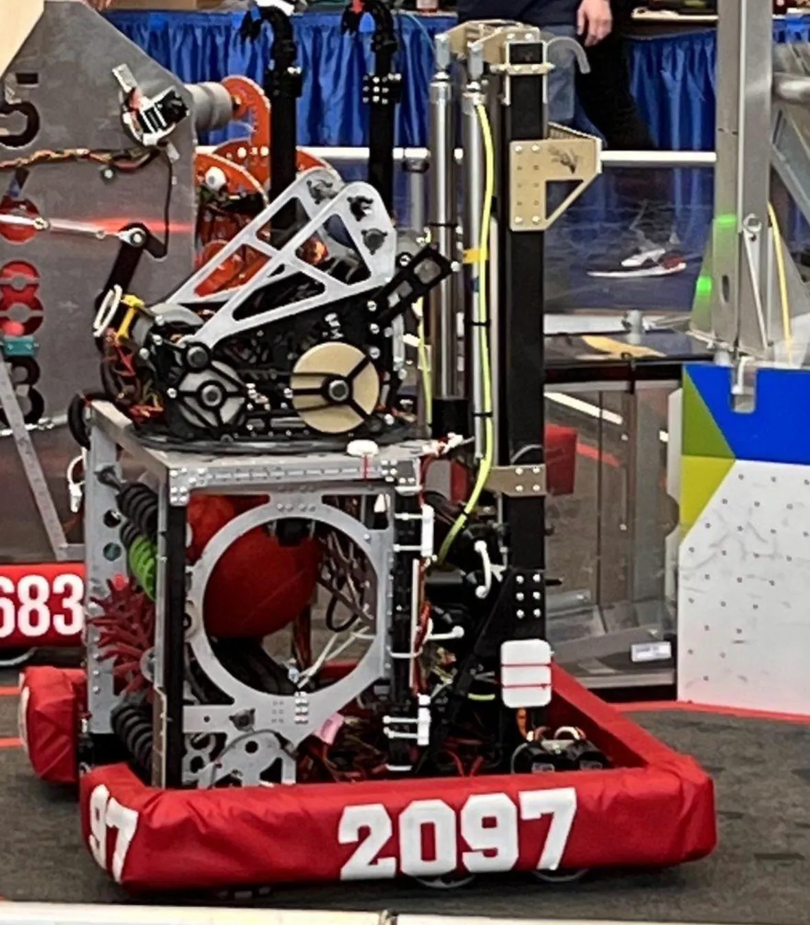 Fig 2. We named our robot “James,” in commemoration of the namesake of our school (James Raisbeck Aviation High School)
Senior Year (2023 Season @ Phoenix Force Robotics)
At the end of my junior year, my peers elected me as Programming Lead, and as such, I was responsible for directing the curriculum for new students. Being a Programming Lead was actually my first foray into STEM education, and it truly led me to understand my own passion for helping others level up their skills and providing them with the tools to create the things they envision in their minds.
Even with many new members possessing strong coding skills, I was involved in crafting numerous subsystems.
Helper Classes
Our robot code was very complex, requiring many thousands of lines of code. However, through the use of utility classes (such as helper classes and wrappers), we were able to streamline the coding process and make the code easily accessible and readable (or at the very least, readable for someone with basic object-oriented programming knowledge).
PFRPIDControllers
We created these special PID controller classes (one for the arm, one for the elevator, and one for simple mechanisms) to combine the voltage feedforward provided by WPILib’s sysid with the control efforts from PID controllers. These wrappers had the added benefit of allowing us to clamp the control effort from the PID controllers. Overall, combining these two typically wordy functions into one reduces bulk in our code and increases readability by a significant margin.
CoordinateMath
One problem we faced when programming the arm was that it operated in a polar coordinate system, with theta representing the angle of the arm and radial distance representing the length of the arm. This is very difficult to control, as the simple act of moving the arm vertically up and down would involve a specific change in length and angle, as otherwise, there would be a change in the horizontal position of the intake. To solve this problem, we decided to find a way to convert from Cartesian velocities (vertical velocity and horizontal velocity). Without getting too far into the details, we followed many red herrings and encountered multiple dead ends in linear algebra and state-space representations. However, our team eventually landed on related rates.
Using established equations that go from polar coordinates to Cartesian coordinates (and vice versa), derive the following equations:
Where is the angular velocity, and is the radial velocity, is the x distance of the arm’s tip from the center of rotation, is the x velocity, is the y distance from the arm’s tip from the center of rotation, and is our y velocity.
Drivebase Subsystem
The drivebase consisted of four modules, each containing a motor and a pneumatic shifter system to switch between our high-friction and non-holonomic traction wheels (represented as DifferentialDrive) and our low-friction and holonomic mecanum wheels (represented as HolonomicDrive). These wheels used WPILib’s sysID characterization, and more importantly, WPILib’s mecanum odometry and inverse kinematics classes. Using the wheel speeds of our Neo motors and the yaw of the robot provided by the Pigeon 2.0, we can predict the robot’s position and direction, and plot that information onto the Driver Station. Through this mapping, we allowed our drivers to know their exact location, even if the robot was in a blind spot.
While in DifferentialDrive mode, it was not possible to feed velocities except from the frame of reference of the chassis itself. However, when using our holonomic drive system, such as our mecanum drive, it was possible to drive relative to the robot OR relative to the field. Of course, we want the drivers to be able to choose, so there was a toggle between the two on our Operator Station. WPILib comes to the rescue (once again) through its kinematics class, which enables us to convert from field-relative velocities (x, y, and angular velocity) into wheel velocities that we can set our motors to using characterization from sysid.
Using the power of PID Controllers, we were able to create a simple command that retrieves pitch (angle upwards/downwards) data from the Pigeon 2.0 and feeds it into a PID controller with a setpoint of 0 degrees (level to the ground). It was a simple yet effective tool in ensuring the robot remains balanced during the endgame.
To create a path for our Drivebase, we utilized Path Planner. This third-party platform allows for path generation and following through its GUI Desktop path creator, as well as its PathPlannerLib library. To generate paths, we crafted Bezier Curves that the robot would travel. Following paths was slightly more difficult, but still manageable. We created a PathPlannerCommandFactory to interface with the library in a more user-friendly and readable way, all of which could be selected from the driver station.
Arm Subsystem
Our arm was able to both telescope AND extend, and we wanted to be able to characterize the necessary efforts on the motors in code. System Identification (sysid) from WPILib made this relatively easy through their sysid program. It enabled us to characterize the motors and the subsystems they power, allowing us to predict their behavior even before the motors began to turn. We did, however, notice a difference in characterization when the arm was retracted versus extended, leading us to create 10 feed forwards, each accounting for slight differences in feed forward values and automatically being selected depending on the angle and extension of the arm.
As discussed in the “Utilities” section, we utilized related rates to convert Cartesian velocities (which are easily understood by humans) into polar velocities (which are more easily understood by our robot). This enabled us to set the velocities of the arm and move the intake up and down without changing the horizontal distance. Given the function, we could easily create a command that takes in the Cartesian velocities and feeds the polar velocities into the subsystem, making fine adjustments far simpler as a driver.
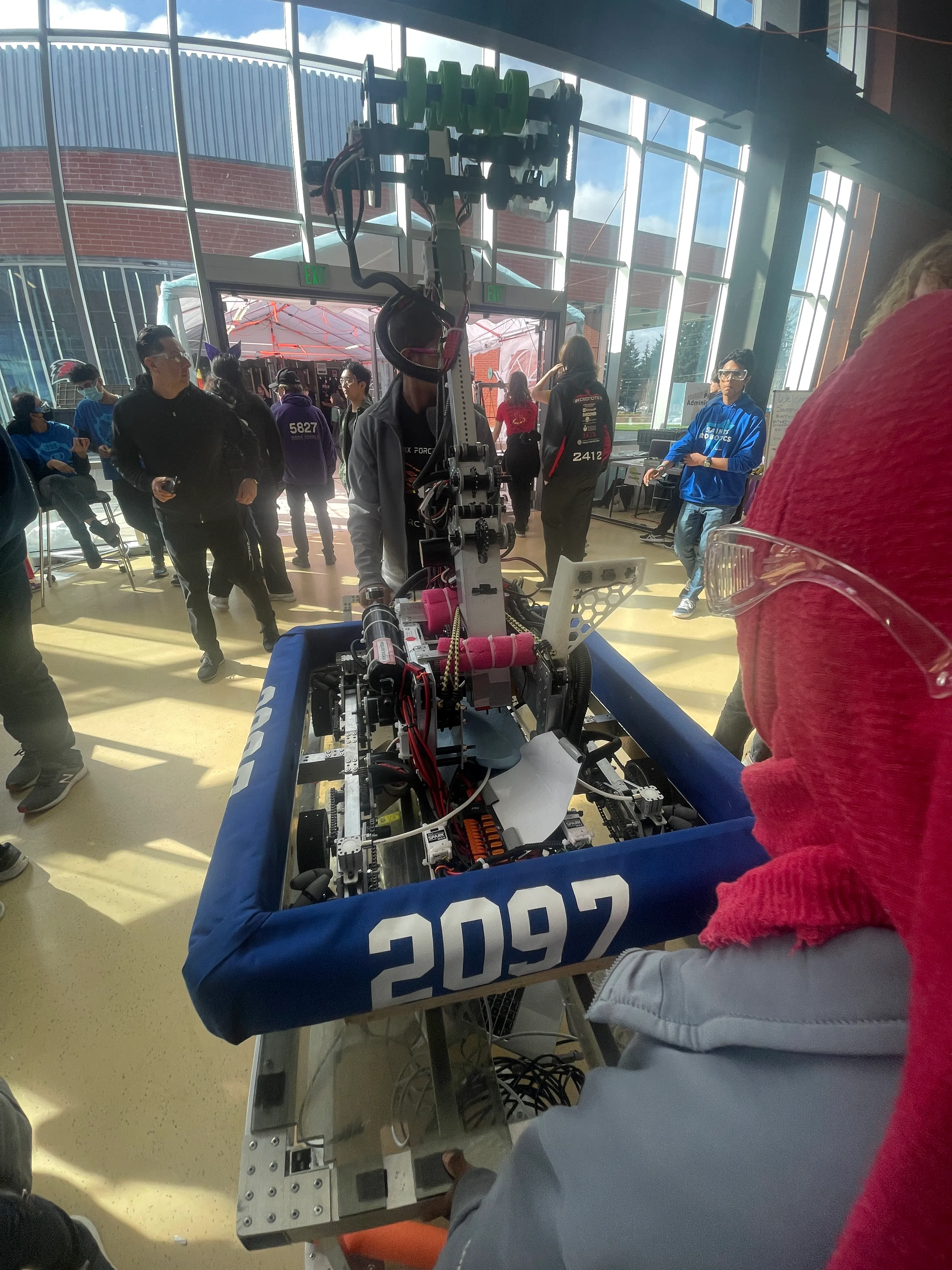 Fig 2. Our robot in all its glory, getting transported to the field during our last competition of 2023.
Conclusion
My time in FIRST robotics was quite the blast, and I always look back at those late nights with my friends quite fondly. Being thrust into such a collaborative, high-caliber team and tackling a challenging engineering problem was a great pleasure, and it really showed me what a career in the industry would be like. To this day, it is this experience that leads me to join engineering clubs at the University of Washington and to seek out internships where collaboration is highly regarded; places where the times do get tough, but where others will be there to assist you through the difficulties. x