
FPGA Snake
5/2024 - 6/2024
Implementation of a custom Snake game using SystemVerilog HDL on a DE1-SoC development board.
Written by: Violet Monserate
System Overview
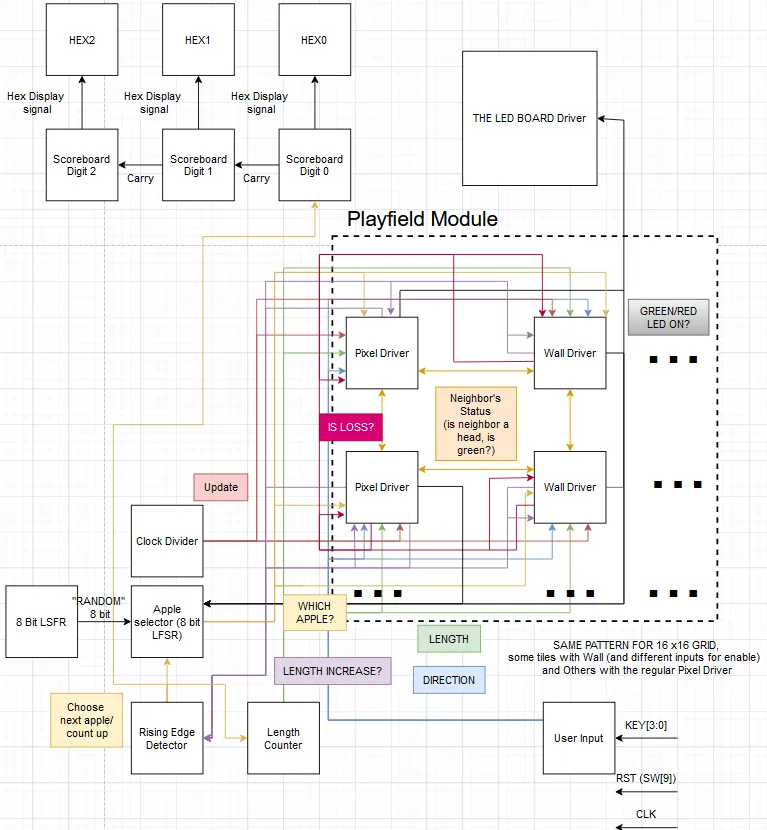 Fig. 1: Block diagram detailing the system architecture of the FPGA Snake game.
Figure 1 illustrates the high-level architecture of the system. User input coordinates with the pixel and wall drivers to manage state transitions. A dedicated length counter tracks the current size of the snake, while an apple selector module identifies the matrix coordinate for the next apple utilizing a pseudorandom number generated by a Linear Feedback Shift Register (LFSR).
The scoreboard modules combine a counter and combinational logic to output a hexadecimal display signal for the active seven-segment displays. An existing LED board driver processes the green and red LED outputs generated by the logic drivers. To regulate the timing of new apple generation, length increases, and score increments, a rising edge detector ensures these events trigger exclusively upon the initial length increase. Additionally, a clock divider is implemented to step down the pixel update rate, functioning approximately 256 times slower than the high-speed circuitry.
The playfield module, which encapsulates the pixel and wall drivers, operates on this divided clock to maintain a playable movement speed. Each pixel driver maintains multiple connections, including adjacent pixel drivers to identify “head” or “body” states, system-wide loss detection signals, the current snake length, directional data, and enable signals.
The output from each pixel module dictates its LED status (red or green), whether it currently acts as the head, and if it is signaling a system loss or a length increment.
User Input
The user input module filters hardware keypresses and utilizes a Finite State Machine (FSM) to generate directional control signals. The leftmost keypress assumes priority, and state transitions remain uniform regardless of the originating state. The current direction is stored in memory; if no keys are actively pressed, the FSM maintains its present state. The directional states are mapped to binary values, with 00 representing up, 01 representing right, 10 representing down, and 11 representing left.
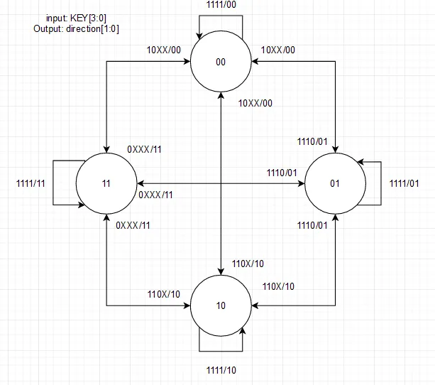 Fig. 2: FSM mapping user input to directional control.
 Fig. 3: Waveform simulation demonstrating FSM transitions during keypress events.
Simulation results verify the proper transition to all directional states and confirm that state retention functions correctly upon key release. Testing encompassed distinct key combinations to account for the HDL implementation’s reliance on sequential conditional statements for hardware keys.
Counters
System implementation necessitated both incrementing and decrementing counters. These modules function identically in operation but feature distinct rollover conditions (underflow versus overflow). The implemented design is dynamically resizable via parameters, though standard testing utilized a 3-bit configuration.
 Fig. 4: Simulation of the increment counter verifying incrementation, default reset, and data loading.
 Fig. 5: Simulation of the decrement counter verifying decrementation, default reset, and data loading.
Simulation confirms that both modules increment and decrement accurately, successfully reset to their default states, and correctly load initialized data.
Decoders
The Apple Selector relies on combinational logic to determine output selection, specifically requiring an 8:256 multiplexer. This was achieved by cascading seventeen 4:16 multiplexers, utilizing one primary multiplexer as the selector for the remaining sixteen.
 Fig. 6: Functional simulation of the 4:16 decoder.
 Fig. 7: Functional simulation of the 8:256 decoder.
Waveform analysis confirms that incrementing the input sequentially shifts the single enabled active bit across the output bus without overlapping signals.
Apple Selector
This module selects a valid, unoccupied matrix square for apple placement when triggered by an enable signal. Combinational logic evaluates whether the pseudorandomly selected pixel is already occupied by a green (active snake) pixel. If the space is vacant, the value is locked in; if the module is not enabled, it retains its existing value. The pseudorandom generation utilizes a parameterized LFSR.
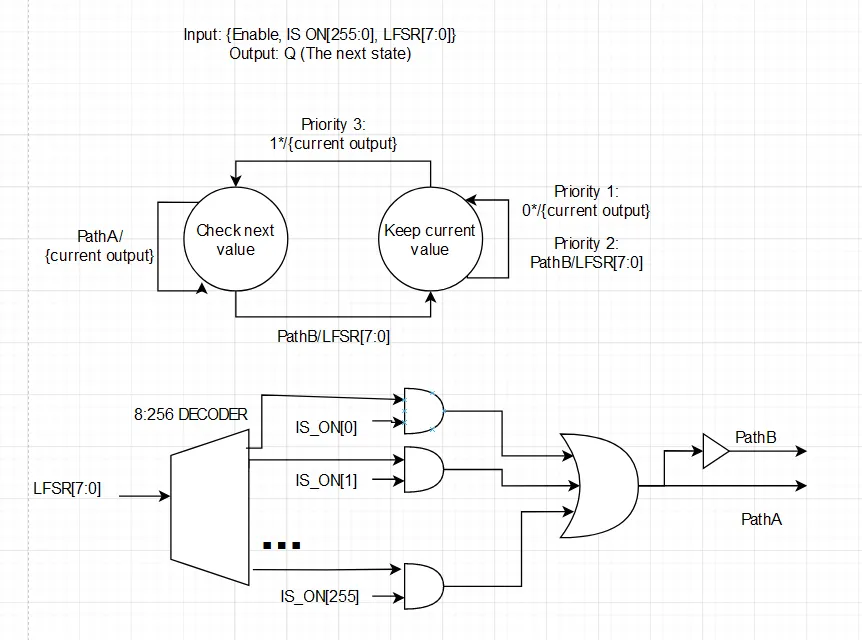 Fig. 8: FSM logic dictating new apple generation and validity verification.
 Fig. 9: Simulation data of the apple selector verifying availability against an occupied array.
During simulation, the module checks generated values against a 256-bit bus representing occupied pixels. If a generated coordinate (e.g., 15 or 31) registers as unavailable, the selector continues polling until it identifies an empty coordinate (e.g., 63).
Scoreboard
The scoreboard modules implement a standard counter and decode the output for compatibility with the seven-segment hexadecimal displays. Upon receiving an enable signal, the module advances to the next numerical value. The scoreboard incorporates dimming functionality through two independent, parameterized reset signals that keep the displays unlit until actively required. Additionally, daisy-chaining is supported by triggering the enable-out bit exclusively during the transition from 9 to 0, which ensures the subsequent display increments accurately during a base-10 rollover.
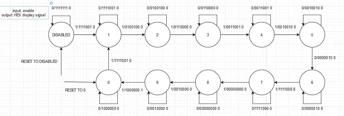 Fig. 10: State machine dictating score incrementation and display rollover.
 Fig. 11: Simulation demonstrating carry-out functionality across multiple displays.
Simulation confirms that connecting HEX2 to the carry-out of HEX1 results in appropriate counter resets at 0 and correct incrementation of the secondary display.
Pixel Module
The pixel module synthesizes multiple environmental inputs to navigate its primary FSM. The transition logic prioritizes direct state commands to optimize hardware resource utilization. The module utilizes several core pixel states. The OFF state serves as the default where the LED remains inactive. The APPLE state signifies a pixel awaiting collection, becoming active based on the selector input. The HEAD state identifies the leading pixel of the snake and dictates forward collision logic. The BODY state represents the active trail, with its duration dictated by the current length parameter. Finally, the LOSS state is triggered upon collision with a wall or an active body pixel.
The transition from OFF to HEAD requires confirmation that a neighboring head pixel is traveling toward the current coordinate. If the current pixel is designated as an APPLE during this transition, a length increase signal is broadcast. Body progression is universally paused for one clock cycle during any length increase event.
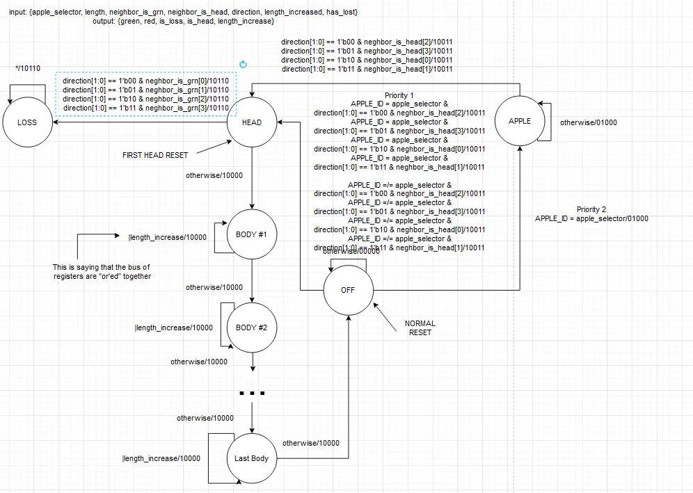 Fig. 12: Primary FSM for individual pixel modules.
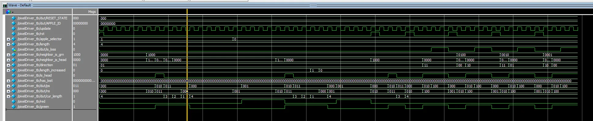 Fig. 13: Functional simulation of pixel state transitions and collision detection.
Simulation illustrates standard body transitions governed by the length parameter (e.g., illuminating a green pixel for precisely four clock cycles). It also validates collision detection protocols and successful apple collection logic.
Wall Module
The wall module replicates the pixel module’s architecture with the addition of a master enable input. When enabled, the module drives both red and green LEDs high (producing an orange visual output on the matrix) to represent an obstacle. Disabling the module forces a standard reset state.
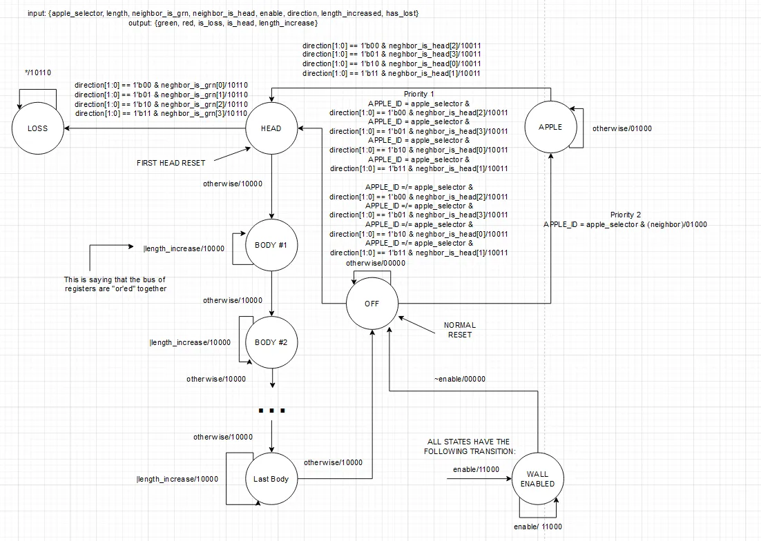 Fig. 14: FSM detailing wall activation and obstacle state management.
 Fig. 15: Simulation confirming expected LED states upon wall activation.
Simulation confirms that toggling the enable signal correctly drives the appropriate LED channels high while maintaining standard collision detection identical to the base pixel module.
Playfield Module
The playfield module encapsulates the generation of all individual pixel modules, streamlining output delivery to the LED boards and facilitating systematic testing. It employs hardware generate blocks to programmatically connect each pixel to its respective neighbors and control inputs. Furthermore, it integrates the physical switches required to toggle obstacle generation across the matrix.
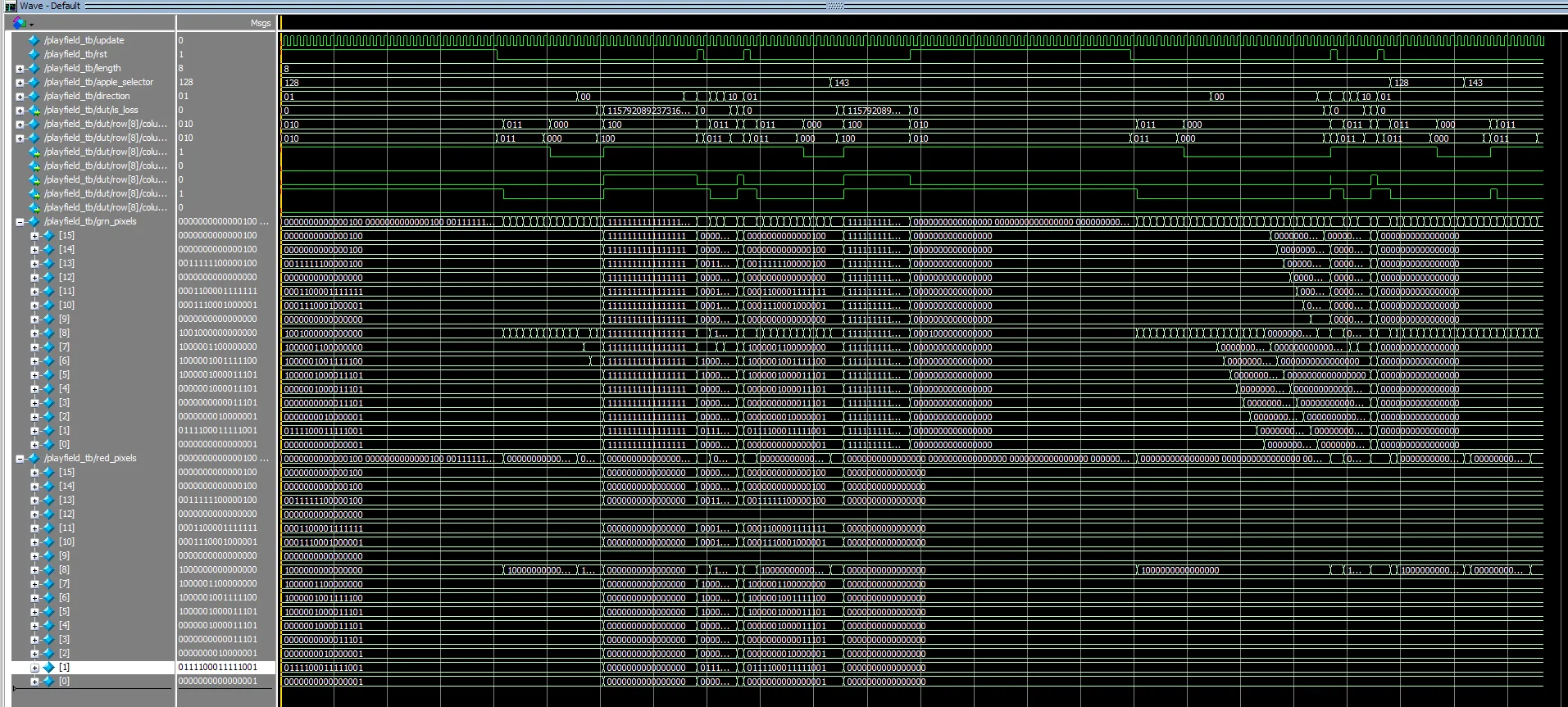 Fig. 16: System-level simulation of the instantiated playfield.
Waveform analysis of the full playfield demonstrates the continuous 2D vector of green pixels translating across the matrix per the clock cycle. It verifies successful apple consumption, the toggle functionality of the physical obstacle switches, and the end-game failure state characterized by total green illumination.
Top-Level Module
The top-level module integrates all discrete sub-modules into a unified cohesive system. This phase ensures all logic buses are appropriately sized and routed between the display drivers, input registers, and game logic units.
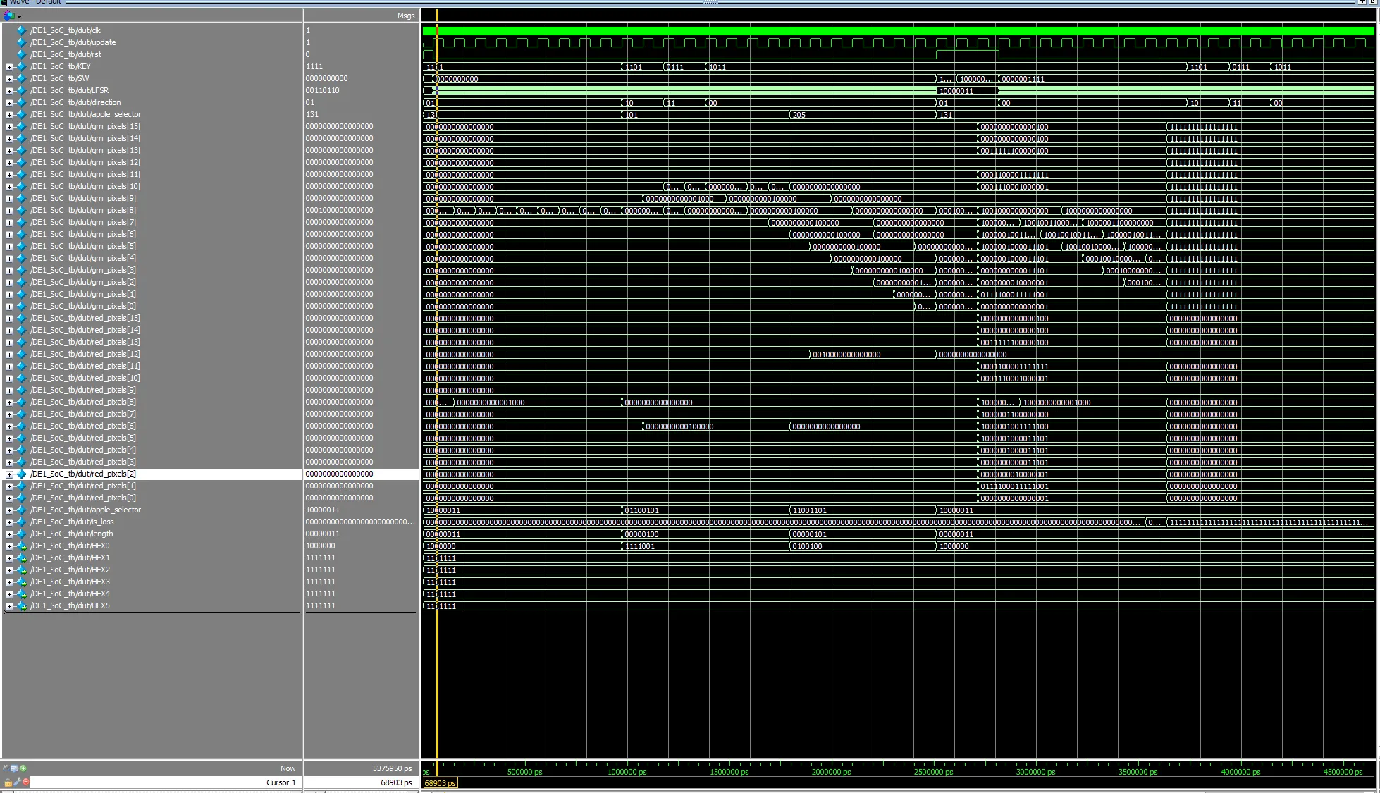 Fig. 17: Comprehensive top-level simulation of active gameplay.
Top-level testing successfully demonstrates a complete gameplay loop: utilizing the hardware reset to initialize a session, directing movement via the keys, and successfully intercepting apples (predicted via the deterministic nature of the LFSR during simulation).
Verification and Testing
Initial verification was conducted strictly within ModelSim to analyze module waveforms against expected logical behaviors. This occurred iteratively, beginning at the component level before progressing to the top-level design.
Following successful simulation, hardware testing involved executing the game on the DE1-SoC board to observe edge cases under physical operation. The hardware edge-case testing protocol involved submitting simultaneous, multi-key inputs during active movement, as well as triggering spontaneous wall generation by enabling obstacles mid-movement. It also included performing mid-game hardware resets and rapidly cycling the reset and enable states. Finally, the LFSR randomness spread was closely observed to ensure no blind spots existed on the 16x16 matrix.
Following minor logic rectifications discovered during physical edge-case testing, the system operated strictly within specified parameters with no anomalous behavior.