
Glasses Capstone
3/2026 - 6/2026
Onboard Computer Vision to detect museum exhibits and play audio descriptions for visitors
Written by: Violet Monserate and Grace Zhou
Product Overview
Museums often rely on visual displays and printed descriptions to communicate exhibit information to visitors. This creates accessibility limitations for visitors with visual impairments, reading difficulties, or language barriers, as well as for users seeking a more interactive experience.
The Assistive Museum Headphone System is a wearable embedded device that automatically detects museum exhibits and provides corresponding audio descriptions to users in real time. The system reduces the need for manual interaction while improving accessibility and user engagement. After a marker is detected, the system temporarily pauses additional scanning until the user manually resets the detection state for the next exhibit.
Museums increasingly rely on digital technologies to improve visitor engagement, accessibility, and educational experiences. Audio guide systems are commonly used to provide additional exhibit information and assist visitors with visual impairments, reading difficulties, or language barriers. Many existing museum guide solutions require visitors to manually interact with exhibits by entering exhibit numbers on dedicated devices, scanning QR codes, or using smartphone applications to access content [1]. More advanced commercial systems, such as Guide-ID, provide interactive and location-aware audio experiences but often require specialized infrastructure and proprietary technology [2]. These approaches can create additional barriers for users seeking a simple and seamless museum experience. The Assistive Museum Headphone System addresses this need by automatically detecting exhibit markers and playing the corresponding audio description without requiring manual exhibit selection, mobile applications, or additional user interaction. By combining computer vision, embedded processing, and real-time audio playback, the system aims to provide a more accessible, intuitive, and cost-effective museum guidance solution.
Product Operation
The user wears or carries the device while walking through the museum. A camera connected to the Raspberry Pi continuously scans the environment for visual markers. When a marker is detected:
- The visual detection software identifies the marker ID
- The marker ID is mapped to a corresponding audio file
- The system alerts the user with a short audio cue to indicate that an exhibit has been detected
- The user can control playback and volume using hardware buttons.
- Audio is delivered through headphones
- The user manually resets the system before scanning resumes for the next marker
UML Diagram
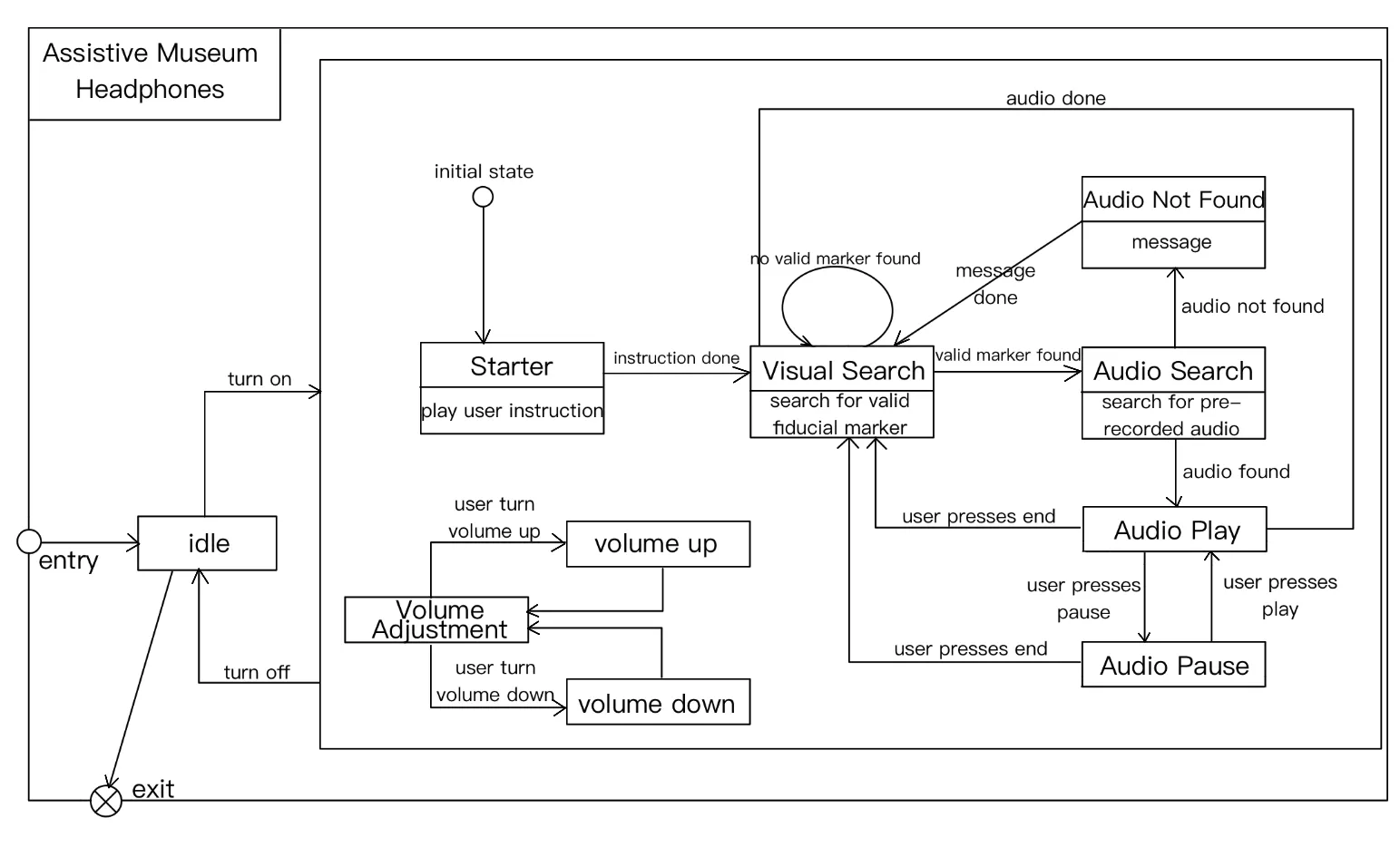 Fig. 1: UML Diagram depicting workflow while using the product.
Constraints and Engineering Standards
Budget Constraints
The project was constrained by a $200 student project budget. Existing development boards and affordable off-the-shelf components were prioritized to minimize cost. With the given budget, we had additional funds to redirect as the project progressed.
Time Constraints
The project was completed in 9 weeks. This limited the complexity of advanced features such as fully autonomous continuous scanning, wireless communication, advanced AI-based object recognition, and cloud-connected functionality. The team prioritized reliable subsystem integration, stable real-time communication, and hardware functionality over adding excessive features.
Hardware Constraints
The project depended on compatibility between multiple embedded platforms and peripherals. Hardware limitations included:
- Limited GPIO availability
- Limited real-time processing capability on STM32
- Physical wiring constraints
- Limited power delivery
Power Constraints
The system was intended to operate as a portable embedded device. Power consumption needed to remain low enough for battery operation (two 3.7V Li-ion batteries).
Environmental Constraints
The system was designed primarily for indoor operation. Camera-based visual detection performance can degrade under poor lighting conditions, excessive glare, motion blur, or when exhibit markers become partially obstructed from the camera’s field of view.
Usability Constraints
The system needed to remain simple for users unfamiliar with embedded devices. To improve usability, the design used minimal physical controls, automatic audio triggering, a straightforward playback interface, and a compact enclosure intended to simplify operation and portability.
Manufacturability Constraints
The enclosure design needed to be easy to print and assemble using available university resources. The team used Fusion 360 CAD tools, standard 3D printer dimensions, and modular enclosure geometry to simplify fabrication and assembly. This includes preventing overhangs, ensuring that designs are roughly prismatic, and only having gradual inclines.
IEEE Standards
The project considered several IEEE-related embedded system and communication principles, including:
- Serial communication reliability
- Embedded real-time task scheduling
- Hardware/software integration practices
Safety Considerations
The design considered:
- Low-voltage operation
- Safe USB-powered components
- Heat management
- Electrical isolation through standard development boards
Trial Designs
Sequential Chart
The sequential chart, shown in Figure 2, illustrates the flow of information through the Assistive Museum Headphone System during normal operation. Images captured by the camera are sent to the Raspberry Pi, where STAG fiducial markers are detected and matched with corresponding audio files stored in the data-mapping system. The Raspberry Pi then streams audio samples through the audio buffer and STM32 using I2S communication before the audio is played through the bone conduction speaker. User button presses are detected by the STM32 and transmitted to the Raspberry Pi through UART communication, allowing playback and volume controls to be managed in real time.
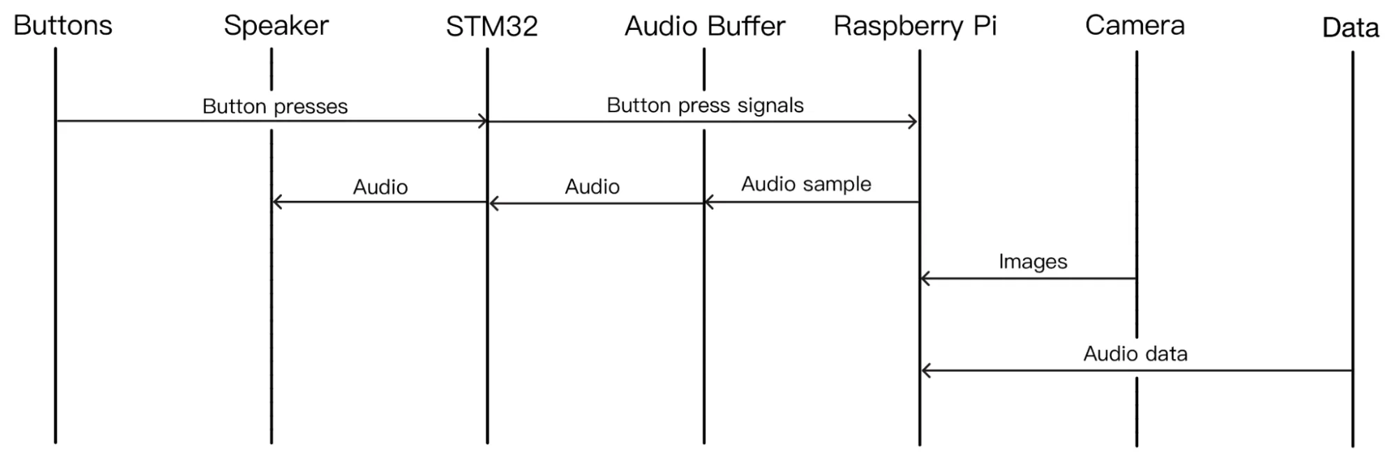 Fig. 2: Sequential Chart
Design Alternatives
Several approaches were considered for exhibit identification, communication, and audio delivery. QR codes, RFID tags, and AI-based object recognition were evaluated as alternatives to STAG fiducial markers. STAG markers were ultimately selected because they provide reliable detection, unique identification, low computational requirements, and straightforward integration with the Raspberry Pi camera system.
Wireless communication methods such as Bluetooth and Wi-Fi were also considered. However, these approaches increase software complexity, power consumption, and system overhead. The final design uses UART communication for playback-control commands and I2S communication for audio streaming due to their simplicity, reliability, and low latency, as well as interoperability with existing STM32 Hardware Abstraction Library (HAL) features.
For audio delivery, both traditional headphones and bone conduction speakers were considered. The final design uses a bone conduction speaker because it allows users to hear audio guidance while remaining aware of their surroundings. Audio is streamed from the Raspberry Pi to the STM32 through I2S communication, where FreeRTOS speaker tasks manage playback.
Final Integrated System Design
The final system integrates a Raspberry Pi 4, STM32F4 Discovery board, USB camera, four control buttons, two bone conduction speakers, and a custom 3D-printed enclosure. The camera, buttons, and bone-conduction speakers are wired to the glasses via a custom wiring harness and held in place with 3D-printed clasps.
The Raspberry Pi runs a Python-based controller responsible for visual marker detection, GUI management, audio file mapping, and playback control. The STM32 manages real-time button-control and speaker tasks using FreeRTOS.
A GUI system allows users to add and modify marker-audio pairs without changing source code. To prevent repeated detections, marker scanning is paused after a marker is detected and resumes only after a manual reset.
System Enclosure Design
The mechanical enclosure was developed to convert the individual electronic subsystems into a more organized and portable prototype. The initial hardware arrangement contained exposed development boards, loose cables, and external peripherals, which made transportation and repeated demonstrations difficult. The enclosure design, therefore, focused on protecting and organizing the central computing and control hardware while keeping the system easily accessible during development.
The enclosure was designed in Fusion 360 as a two-part structure consisting of a bottom case and a removable top cover. The bottom case contains designated spaces for the Raspberry Pi 4, STM32F4 Discovery board, and battery or power-routing components. The Raspberry Pi and STM32 were arranged side by side rather than stacked vertically so that their ports could face the external enclosure walls and remain accessible.
Enclosure Iteration Process
The first CAD layout focused on creating an open-base enclosure large enough to accommodate the two boards and power components. Internal rectangles were then used as placement guides for the Raspberry Pi, STM32, and battery. After deciding not to use screws, the mounting approach was revised from screw standoffs to anti-slide rails. This change made the enclosure easier to assemble and better suited for a prototype requiring frequent hardware access. Additional design revisions included planning openings for external cables and user-accessible connections. The enclosure needed to support the project’s electrical and interaction requirements, so the mechanical layout was coordinated with the locations of the USB, Ethernet, power, audio, and control-wire connections.
CAD Designs
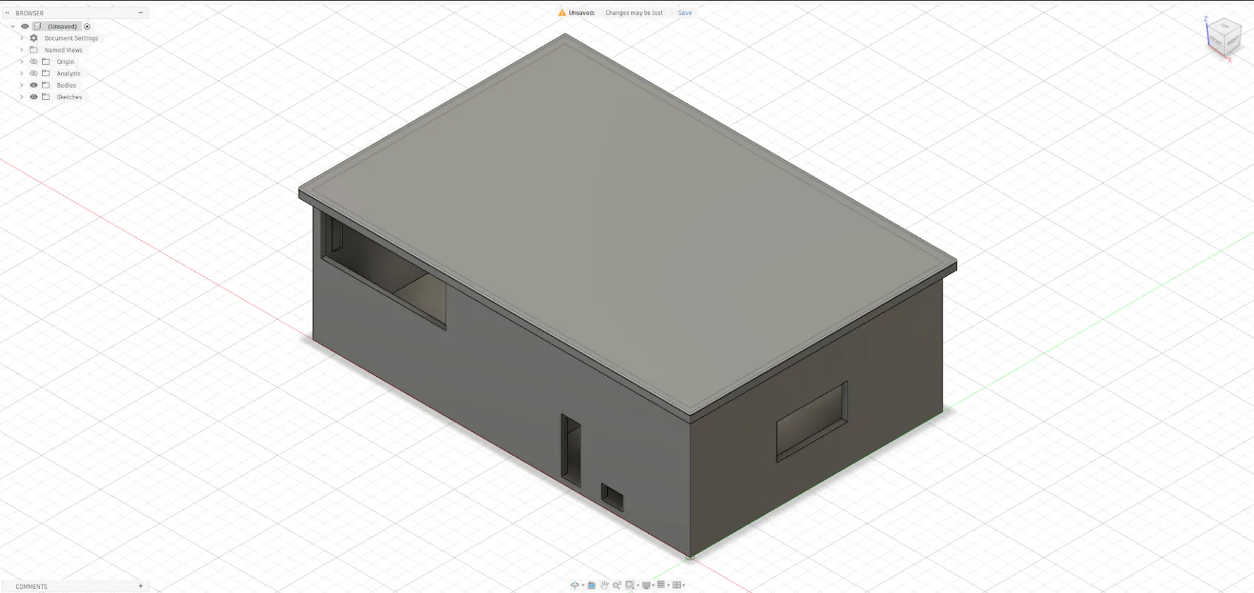 Fig. 3: Enclosure CAD Design
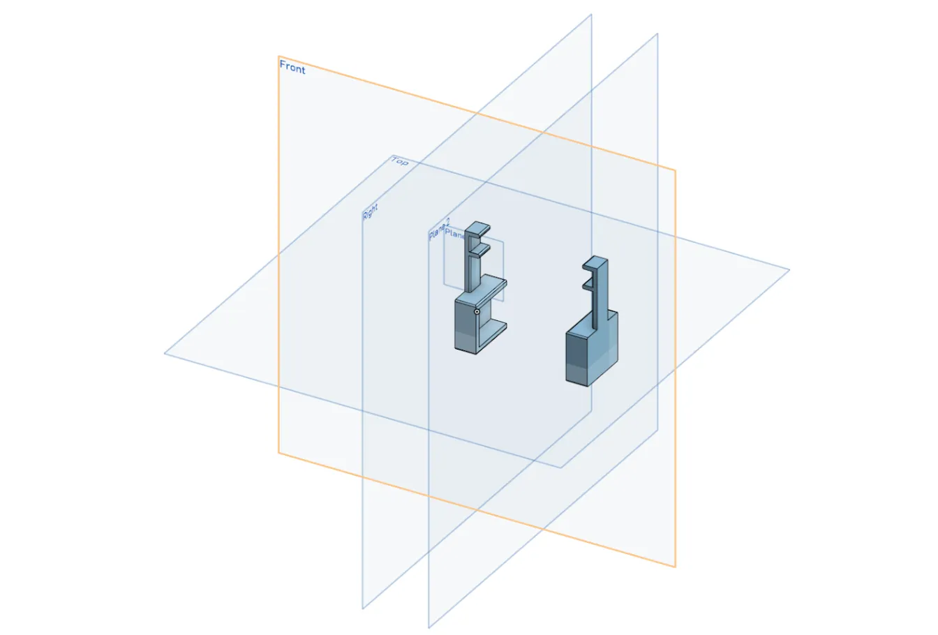 Fig. 4: Bone Conductor Speaker Holder CAD Design
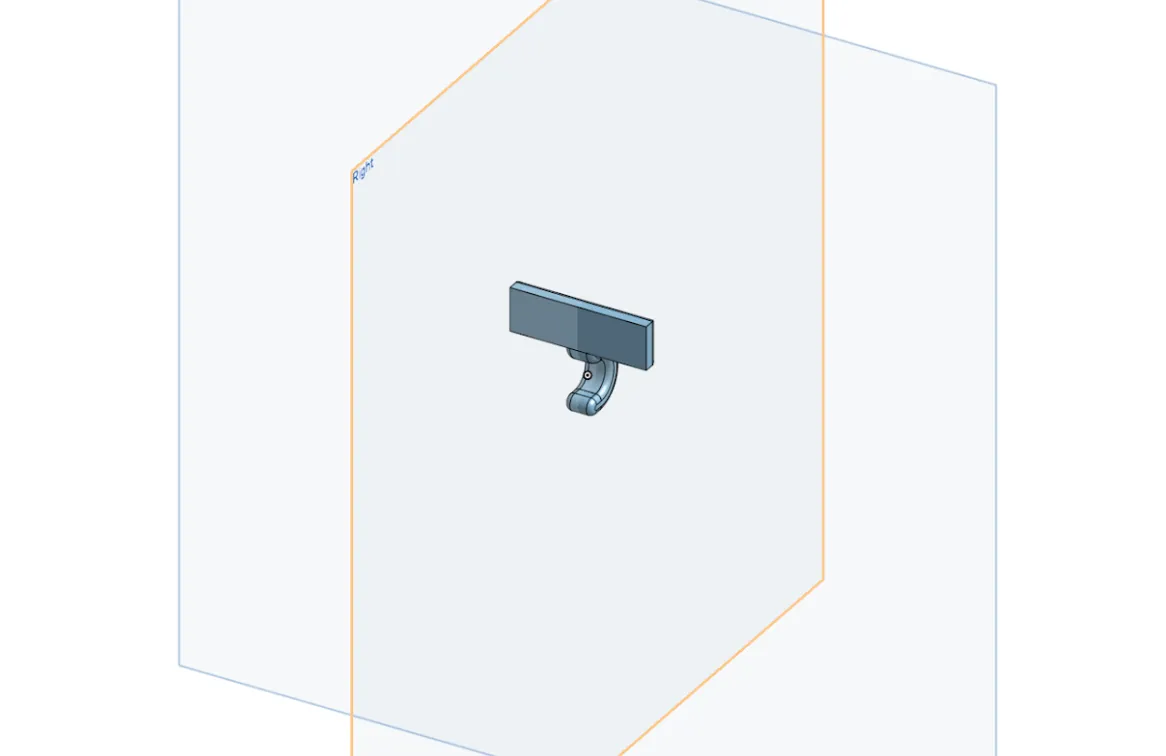 Fig. 5: Camera Holder CAD Design
Final Physical Product
The final Assistive Museum Headphone product is shown in Figures 6 and 7. Figure 6 shows the custom 3D-printed enclosure containing the Raspberry Pi 4, STM32F4 Discovery board, battery, and supporting wiring. Figure 7 shows the wearable glasses assembly, which uses custom 3D-printed mounts to secure the USB camera and bone conduction speaker. Together, these components form a portable assistive museum guidance system that automatically detects STAG fiducial markers and delivers corresponding audio descriptions to the user. The completed prototype demonstrates the successful integration of computer vision, embedded control, real-time audio streaming, and mechanical packaging into a single assistive technology platform.
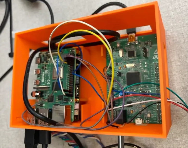 Fig. 6: Assistive Museum Headphone Final Product - Enclosure Internal View
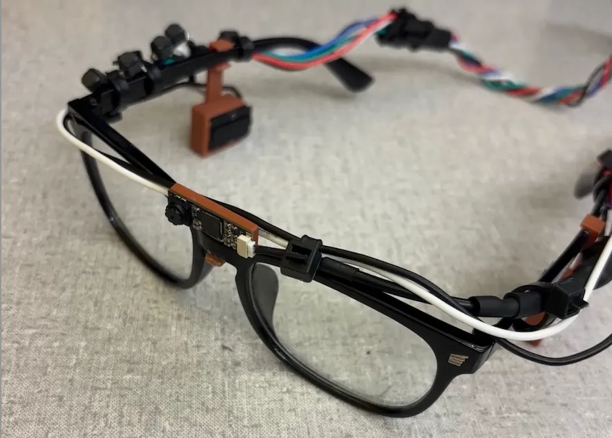 Fig. 7: Assistive Museum Headphone Final Product - Wearable Prototype
Impact and Consequences
The Assistive Museum Headphone system has potential societal value because it provides audio-based access to exhibit information without requiring a visitor to continuously read signs or interact with a phone. This may improve museum experiences for visitors with visual impairments, reading difficulty, language barriers, or users who prefer audio-based learning. The custom enclosure directly improves usability by consolidating separate exposed circuit boards and wiring into a more portable, organized prototype.
However, the given form factor is a potential problem for accessibility and universality. The glasses fit fairly tightly and were a trouble to put on and take off. This also led to issues with contact with the speakers and thus getting adequate volume. Similarly, the device’s glasses form factor makes it intuitive but may pose issues with proper operation for folks who already wear other face coverings or headwear (e.g., glasses, hijab, face mask). As such, future iterations ought to consider ways to attach the device and speakers without interfering with other components. This could include the “halo” design that was forgone in early discussions due to questions around fragility and ease of use.
From an ethical perspective, the camera-based detection system may raise privacy concerns, as museum visitors may worry that the device is recording them or collecting images. To reduce this concern, the system processes marker detection locally, avoids storing unnecessary images or video, clearly labels the device as a marker-detection audio guide, and notifies users that the camera is used only to identify exhibit markers and that the data is never stored in persistent memory. In a more industrial product, a potential solution could be to remove any wireless interfaces that could be attack vectors for bad actors. Others might worry that the data will be used to train facial recognition LLMs without consent. We ought to provide signage that clarifies that this is not something our product condones or allows.
From a product design perspective, the enclosure improves reliability and presentation quality. Loose circuit boards and exposed cables are difficult to carry and more likely to disconnect during demonstration or use. Housing the Raspberry Pi, STM32, power components, and wiring in a case reduces accidental movement and helps preserve the physical arrangement needed for reliable operation. The removable tray-based design also supports repair and iterative development because damaged or updated components can be replaced without destroying the enclosure. Unfortunately, due to the lab’s requirement that soldering be avoided on the STM32F4DISCOVERY, header wires were used. In further iterations, this can be completely avoided by solely using soldering or locking connectors for all connections.
Safety concerns were also considered because the prototype contains electronics, cables, batteries, and audio output hardware. Loose wires or exposed boards could disconnect during use, and excessive audio volume could distract users from their surroundings. The enclosure reduces these risks by consolidating the Raspberry Pi, STM32, power components, and wiring into a single enclosure. Future versions should include cable strain relief, smoother case edges, ventilation near the Raspberry Pi, secure battery retention, labeled ports, and a maximum safe volume setting.
The design process also involved environmental tradeoffs. The 3D-printed PLA enclosures increased material consumption and generated substantial plastic waste across several unsuccessful iterations. To reduce this consequence, the design should be verified in Fusion 360 before printing, and small tolerance or port tests should be printed before producing the full case. PLA was selected because it is readily printable and suitable for prototype fabrication, but future versions could consider more durable materials or reusable modular enclosure parts.
From an economic perspective, the enclosure uses low-cost additive manufacturing rather than custom-manufactured housing, making the prototype practical for a student project and potentially scalable to small-batch educational or museum demonstration devices. However, a commercial version would require additional development in durability, thermal testing, user comfort, accessibility evaluation, electrical safety, and long-term battery management.
Overall, these concerns can be reduced through more mindful design choices, including local image processing, minimal data storage, reusable or recyclable enclosure materials, test prints before full fabrication, secure cable routing, safe low-voltage power design, improved ventilation, and user-centered testing with museum visitors.
Conclusions and Recommendations
The enclosure design satisfied the primary design objective of organizing the major components while keeping them removable for debugging. The decision to use anti-slide rails instead of screws was appropriate for the prototype stage because it simplified assembly and reduced the risk of damaging or obstructing the development board’s hardware. The next mechanical priority is to complete or verify all port cutouts and ensure that power, programming, communication, and audio cables can be attached without opening the enclosure.
The project demonstrated the feasibility of an assistive museum audio system that combines visual marker detection, local audio-file mapping, embedded user controls, speaker output, and portable mechanical packaging. The enclosure portion of the project addressed the practical challenge of integrating multiple development boards and cables into a single usable system. Using Fusion 360 and additive manufacturing, a custom case could be designed to accommodate the specific dimensions and access requirements of the Raspberry Pi 4, STM32F4 Discovery board, power components, and control wiring.
Several sources of error or uncertainty should be considered. Measurements made with a ruler rather than a caliper may result in inaccurate board or connector clearances. 3D printing tolerances may cause rails or cutouts to fit more tightly than expected. Wiring positions may also change during final integration, potentially requiring additional cable-routing space. These issues can be reduced by carefully measuring the final hardware configuration, providing approximately 1–2 mm clearance around removable parts and cable openings, test-printing critical connector regions, and revising the CAD model after the first physical fit test.
Future improvements should include a more compact enclosure, improved ventilation near the Raspberry Pi, a better removable lid mechanism, labeled external ports, integrated cable strain relief, and a secure but removable battery holder. A later product version could also integrate the electronics into a smaller custom PCB or wearable housing suitable for regular museum use.
As a team, this project reinforced our skills in a variety of areas, including soldering, 3D modeling, high-level Python programming, microcontroller development, embedded systems integration, and hardware prototyping. Throughout the design and implementation process, we gained valuable experience in troubleshooting both software and hardware issues, coordinating subsystem integration, and managing design trade-offs between functionality, portability, and ease of use. The project also highlighted the importance of iterative design, testing, and communication within a multidisciplinary engineering team. Overall, the successful development of the assistive museum audio system demonstrated not only the technical feasibility of the concept but also the practical engineering skills required to transform an idea into a functional prototype.
References, Acknowledgments, and Intellectual Property
References
[1] International Council of Museums (ICOM), “ICOM G20: Digital tools for cultural protection and promotion,” ICOM, Nov. 16, 2021. [Online]. Available: https://icom.museum/en/news/icom-g20-digital-tools-for-cultural-protection-and-promotion/. [Accessed: Jun. 6, 2026].
[2] Guide-ID, “Guide-ID - Interactive audio tours and visitor experiences,” [Online]. Available: https://www.guide-id.com/. [Accessed: Jun. 6, 2026].
[3] B. Benligiray; C. Topal; C. Akinlar, “STag: A Stable Fiducial Marker System,” Image and Vision Computing, 2019.