
FPGA Music Editor
6/2026 - 6/2026
Designing an FPGA music editor with a rendering engine, VGA buffer, and audio pipeline for EE/CSE 371
Written by: Violet Monserate
Design Procedure
In this lab, we engineered a digital synthesizer and music editor on the DE1-SoC by integrating direct digital synthesis (DDS) audio generation with a VGA rendering engine. The architecture relies on multidimensional memory fetching, algorithmic state machines, and data paths to generate concurrent audio voices and graphical user interfaces.
Task 1: Rendering Engine
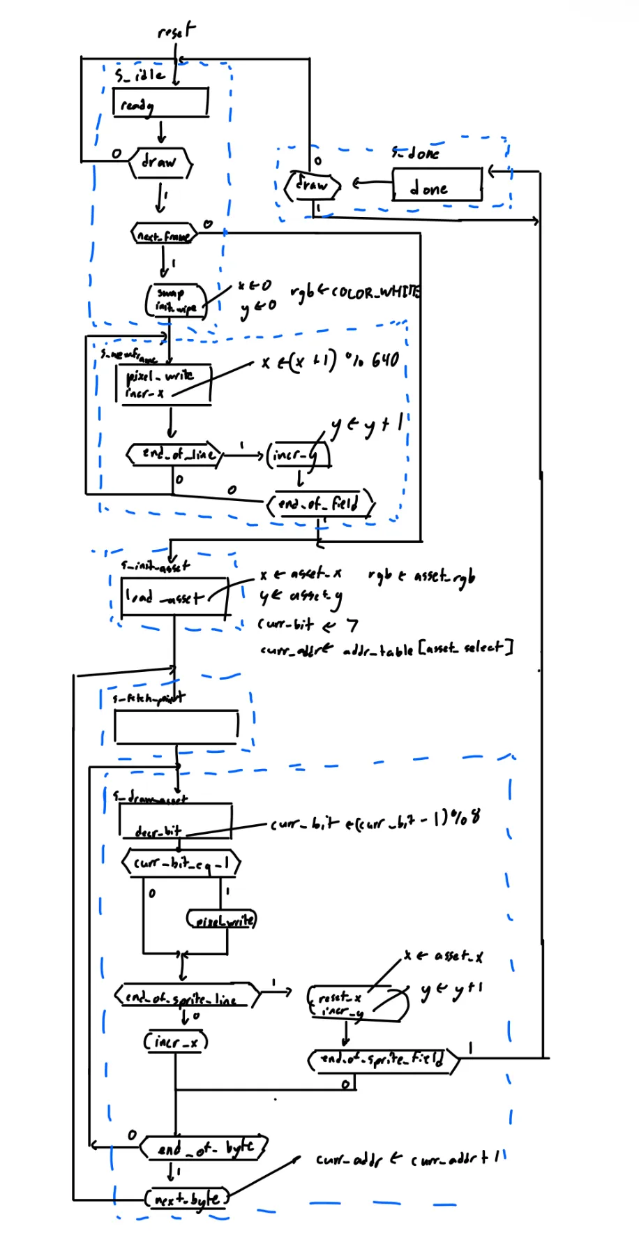 Figure 1: ASMD chart of the rendering engine. The datapath acts as a hardware-level API, transitioning from an idle state upon receiving a draw command, decoding the requested asset_t shape, and iterating through relative pixel coordinates to plot the asset before asserting done.
The first objective was to establish a rendering engine capable of drawing musical assets (such as clefs, rests, and note heads). Algorithmic shape generation is insufficient for standard musical notation. To address this, we designed the rendering_engine. By offloading pixel layouts into static memory, the UI orchestrators only need to provide three parameters: an asset_t enum (shape index), a color_t enum (color), and an (x, y) coordinate pair (origin point).
Python Asset Generation and Byte Ordering
To automate asset creation, we developed a Python script that takes black-and-white image files, crops them to their bounding boxes, and flattens the 2D pixel arrays into 1D bit strings.
To optimize M10K block RAM utilization and fit all assets in a single main_memory module, the script chunks these bits into 8-bit strings and exports them as hex values into a Memory Initialization File (.mif). We chose a Most Significant Bit (MSB)- to-Least Significant Bit (LSB) ordering (curr_bit decrements from 7 down to 0) so that the monitor’s left-to-right drawing order matches the bitwise reading order of the memory byte.
To handle varying asset sizes without padding, we partitioned the ROM into four tables. width_table and height_table return bounding box dimensions based on the asset_select enum. addr_table returns the 16-bit starting address in main memory. Finally, main_memory contains the sequential pixel data.
State Machine and Algorithmic Flow
Translating these packed bytes into VGA pixels requires an ASMD protocol using draw, ready, and done signals.
The state machine rests in idle until draw is asserted. It transitions to S_init_asset, asserting that load_asset is loaded. This synchronously locks in the asset_x, asset_y, and asset_color inputs, resets the bit counter (curr_bit = 7), and points the curr_addr register to the asset’s starting address. Upon reaching S_fetch_point, a 1-clock-cycle memory delay allows the main_memory ROM to latch the data at curr_addr and present curr_byte to the datapath.
The next state, S_draw_asset, acts as the main loop. The FSM evaluates the bit at curr_byte[curr_bit]. If the bit is 1 (curr_bit_eq_1), the engine asserts pixel_write, sending the x, y, and color to the VGA framebuffer. The FSM increments x across the sprite width, resets x, increments y at the end of a line, and decrements curr_bit. If curr_bit hits 0, the FSM asserts next_byte to increment the memory address and loops back to S_fetch_point.
We integrated a screen-clearing subroutine. If next_frame is asserted while draw is asserted, the FSM enters S_new_frame. It sweeps across the 320x240 coordinate space, writing a default color to every pixel.
Decoupling Shape and Color
The memory only stores binary masks (1 for draw, 0 for transparent). The engine multiplexes the color_t input onto the active pixels. This architecture allows us to use the same ROM memory footprint to draw notes of varying colors by changing the color_t input.
Task 2: VGA Buffer
Our sheet music editor requires drawing a multi-layered UI. If we used a single framebuffer, the VGA monitor would scan the memory while the rendering engine was still drawing, resulting in visual flickering and screen tearing. To prevent this, we implemented a double-buffered architecture.
Staff-Provided video_driver
The provided video driver requests a specific coordinate (320 x 240 in our case) and applies the corresponding color to the output pins. Because this device has no storage, we created a wrapper that includes our double buffers to provide a registered output.
M10K-Friendly Unpacked Memory Array
We created two separate framebuffers. Using 1-D arrays allows the compiler to assign the framebuffers to the M10K memory modules. We read from the arrays synchronously to ensure compatibility with M10K block parameters.
logic active_buffer;
// M10K Friendly Flat Arrays (1D) for flawless synthesis
color_t framebuffer0 [76799:0];
color_t framebuffer1 [76799:0];
...
always_ff @(posedge clk50) begin
    // Strictly synchronous reads from BOTH memories into physical registers
    read_data0 <= framebuffer0[read_address];
    read_data1 <= framebuffer1[read_address];
end

// Safely multiplex the registered outputs (NOT the memory itself)
assign pixel_read = active_buffer ? read_data1 : read_data0;
Figure 2: Code featuring the changes made to ensure that memory would be utilized, saving the more general-purpose ones for other applications throughout the project.
Coordinate Downscaling for Memory Efficiency
To reduce block RAM consumption, we render the logical UI at 320×240 and output the standard 640×480 VGA signal.
logic [9:0] driver_x;
logic [8:0] driver_y;

logic [16:0] read_address;
color_t pixel_read;
// Calculate 1D address for the driver's scanning coordinates
assign read_address = driver_x + (driver_y<<8) + (driver_y<<6);
Figure 3: We must flatten the 2d coordinate system into a 1D array to easily and efficiently find the given color_t.
The 3-Bit Color Palette LUT
To reduce memory width, we altered the framebuffer to store a 3-bit color_t enum instead of 24-bit RGB values.
// Look-Up Table (3-bit color palette -> 24-bit RGB)
rgb_t vga_rgb_out;
always_comb begin
    case (pixel_read)
        BLACK:  vga_rgb_out = BLACK_RGB;
        WHITE:  vga_rgb_out = WHITE_RGB;
        RED:    vga_rgb_out = RED_RGB;
        // ...
        default:vga_rgb_out = BLACK_RGB;
    endcase
end

// Routing final decoded color to the DAC
assign VGA_R = vga_rgb_out.r;
assign VGA_G = vga_rgb_out.g;
assign VGA_B = vga_rgb_out.b;
Figure 4: This combinational Look-Up Table is our final memory optimization. Rather than storing massive 24-bit RGB values inside the M10K blocks, we store a lightweight 3-bit enum and generate the heavy 24-bit signals dynamically right before they exit to the DAC.
Finally, all of the data is passed to the video_driver, which then produces the necessary VGA signals for the top-level module.
Task 3: ADSR Envelope
To make our synthesized audio mimic the natural dynamics of physical instruments, we implemented an Attack, Decay, Sustain, Release (ADSR) envelope generator. A raw digital oscillator generates a static, continuous tone; the ADSR envelope acts as a dynamic volume multiplier, shaping the onset (Attack), the initial fade (Decay), the holding volume (Sustain), and the final fade-out (Release) of the note.
Bresenham Linear Interpolation
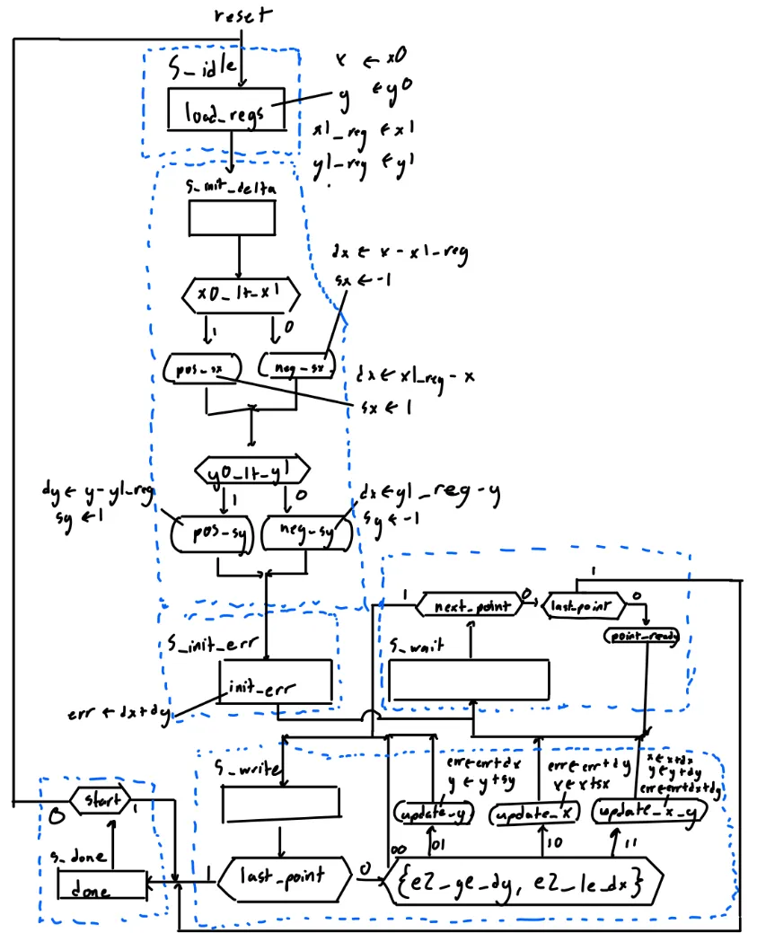 Figure 5: ASMD for our updated Bresenham’s Line Drawer algorithm. The main changes from Lab 5 are the inclusion of the S_wait state, in which we wait until _next_point is high before generating the next output. In addition, there is a transition to the S_idle state and a deassertion loop.
Calculating volume slopes using division is resource-intensive. Instead, we reused the line_drawer module from Lab 5 as a linear interpolation engine. By treating time as the X-axis and volume as the Y-axis, the line drawer computes the volume steps for a linear fade. The datapath routes configuration dials (e.g., attack_time) into the inputs of the line drawer, and the Y-coordinate output serves as the volume multiplier.
State Machine and Timing Synchronization
The ADSR_envelope_control FSM orchestrates the transition between the four phases. In a load state (e.g., S_load_decay), the datapath routes parameters to the line drawer and pulses the start signal. The FSM enters a wait state and asserts next_point to the line drawer when the global tick signal goes high. When the line drawer asserts done, the FSM transitions to the next load state.
Handling Arbitrary and Fixed Durations
In sustained mode (is_sustained = 1), the FSM halts at S_wait_note_off, holding the sustain volume until the user releases the key. In percussive mode (is_sustained = 0), the FSM advances through a fixed-duration sequence before entering the release phase.
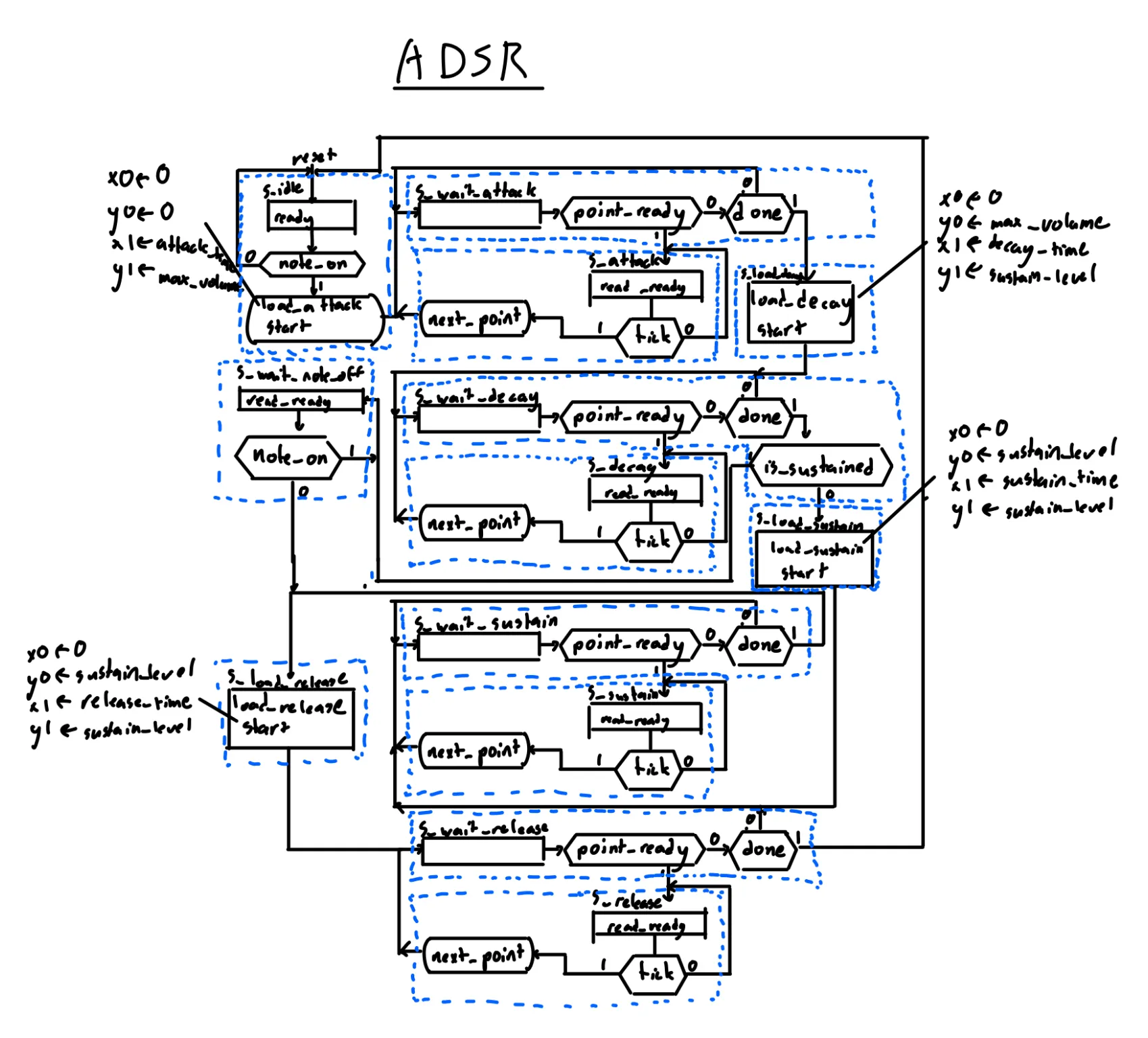 Figure 6: ASMD for the updated ADSR envelope module. Note how repetitive the states are, and how it will often transition between states on the same sort of signal, with the only difference being what sort of value is being calculated in the line drawer.
Task 4: Audio Generator
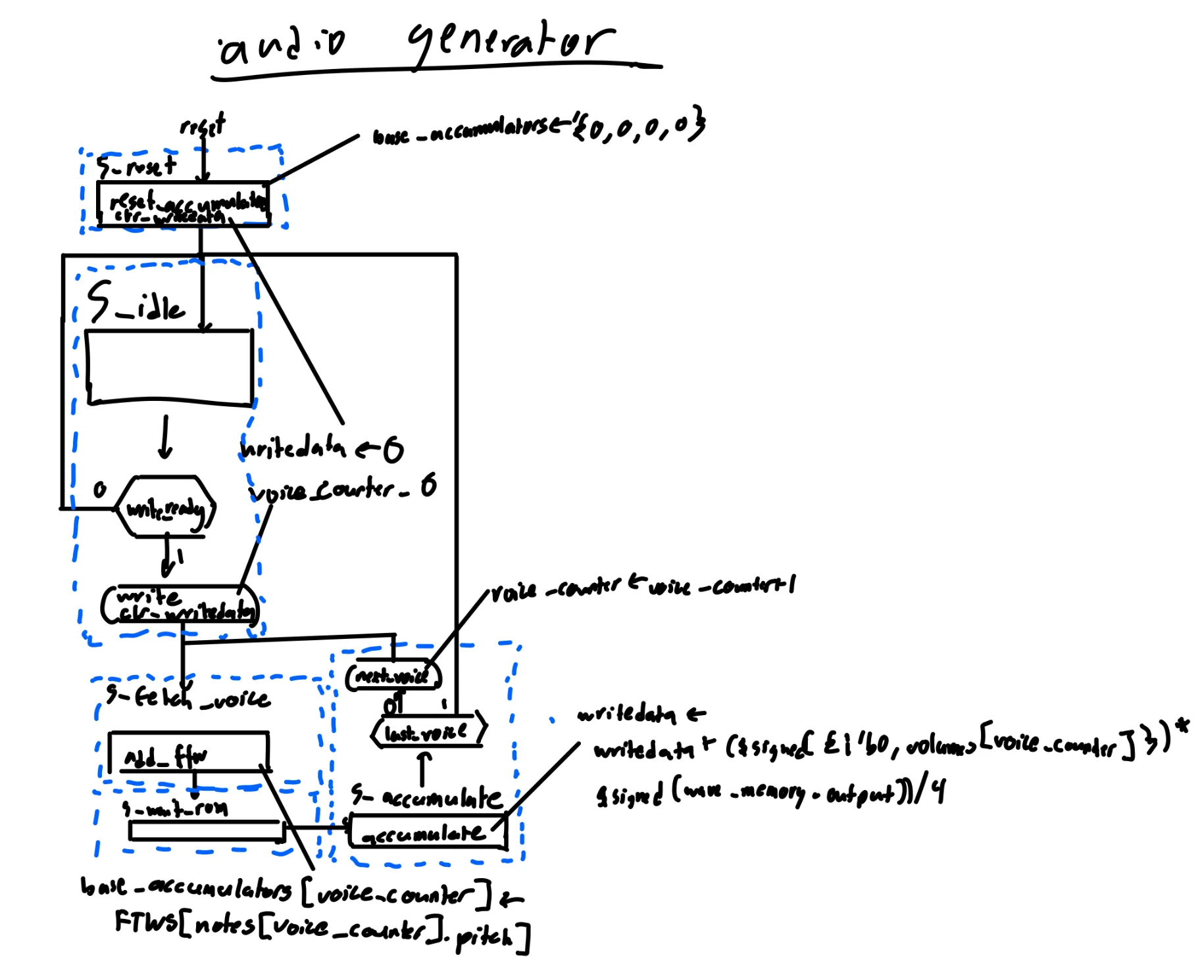 Figure 7: ASMD chart of the overall audio generator using DDS. The control unit iterates through each active voice, fetches the corresponding waveform data from ROM, applies the ADSR envelope multiplier, and accumulates the results into a single mixed output sample.
To support multiple simultaneous notes, we implemented a Direct Digital Synthesis (DDS) architecture. A single processing loop calculates and mixes active voices sequentially within the 50MHz clock domain before the 48kHz audio CODEC requires the sample.
Phase Accumulation and ROM Addressing
Pitch generation uses a lookup table of Frequency Tuning Words (FTWS). When a note is played, its FTW is iteratively added to the 32-bit phase_accumulators.
To convert this phase into a physical wave, the accumulator data is routed into a wave_memory ROM, which stores 512 samples for several waveform shapes. We constructed a 12-bit ROM address by concatenating the 3-bit waveform_t enum with the top 9 bits of the phase accumulator:
We constructed a dynamic 12-bit ROM address by concatenating the 3-bit waveform_t enum with the top 9 bits of the phase accumulator:
assign address = {notes[voice_counter].waveform, phase_accumulators[voice_counter][31:23]};Figure 8: The concatenation of the phase accumulator and the address itself to create the address in the wave_memory address, which holds the sample itself.
DSP Mixing and Overflow Prevention
To prevent integer overflow from summing four 16-bit signed audio waves, the datapath scales the output:
writedata <= writedata + ($signed({1'b0, volumes[voice_counter]}) * $signed(wave_memory_output)) / 4;Figure 9: All necessary scaling on the raw sample is performed here and accumulated into the eventual write data output.
The 16-bit wave data is multiplied by the 8-bit dynamic volume from the ADSR_envelope. Padding the volume with a leading zero prevents phase inversion. Dividing the accumulated result by 4 guarantees the output will not exceed the 24-bit boundary.
State Machine and Algorithmic Flow
The FSM rests in S_idle until the CODEC asserts write_ready. It transitions to S_fetch_voice, signaling the datapath to add the FTW to the accumulator. S_wait_rom acts as a 1-clock-cycle delay for the ROM output. In S_accumulate, the FSM adds the scaled waveform to the writedata register. The FSM increments voice_counter and loops back to S_fetch_voice until all voices are processed, then returns to S_idle and asserts write.
Task 5: Audio Controller
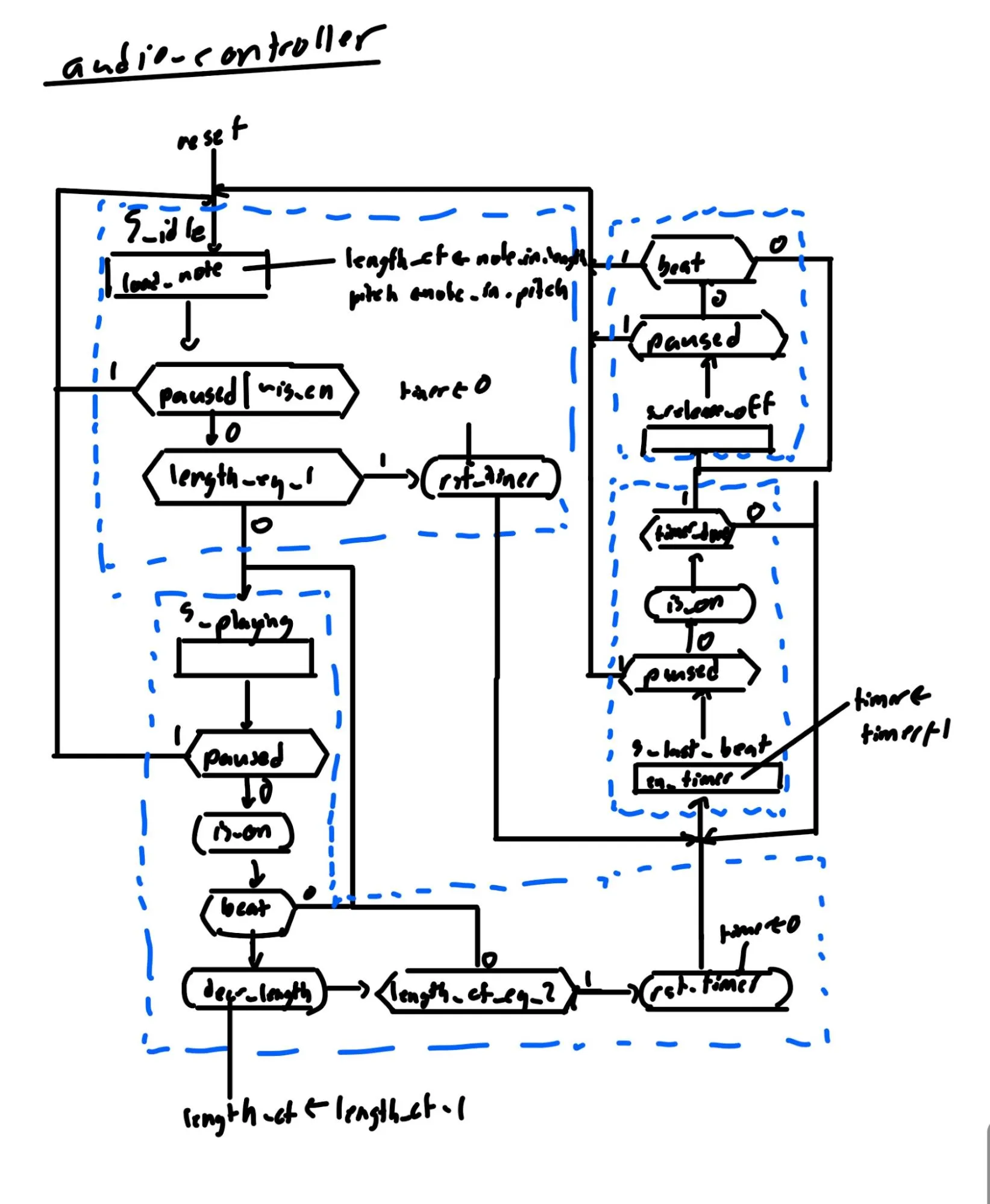 Figure 10: ASMD chart of the audio controller. The control unit manages the timing and sustain of a single musical note, transitioning through idle, playing, and release states based on the global beat pulse and the note’s specified duration.
The audio controller manages note timing, synchronizing playback with the hardware beat generator.
Beat Generator
A beat_generator module divides the 50MHz clock down to 120 Beats Per Minute using a 25-bit counter. It pulses a beat signal high for one clock cycle every 25,000,000 ticks. When playback is paused, the counter clears to zero, ensuring the sequencer restarts upon re-enabling.
Parallel State Machines
To support multiple voices with independent timings, we used a generate construct to instantiate four parallel timing FSMs.
generate
    for (i = 0; i < NUM_VOICES; i++) begin : voice_gen
      // control -> datapath
      logic is_on, load_note, decr_length, rst_timer, en_timer;
      // datapath -> control
      logic length_eq_1, length_ct_eq_2, is_en, timer_done;
      audio_controller_control c_unit (.*);
      audio_controller_datapath  #(TIMER_DURATION) d_unit (.*);
Figure 11: The referenced generate statement that allows us to create all the requisite control and datapath modules automatically.
Articulation and the Fractional Release Timer
To ensure distinct note separation, we decoupled the musical beat from physical duration using a timer (TIMER_DURATION, set to 250ms). The datapath cuts the note short before the next beat arrives, dropping is_on to force the ADSR envelope into its release phase.
State Machine and Algorithmic Flow
The FSM rests in S_idle. When an enabled note arrives, it evaluates its length. If the note is one beat long, it jumps to S_last_beat_on, triggering the ADSR attack. After 250ms (timer_done), it transitions to S_release_off. For multi-beat notes, it transitions to S_playing and decrements length_ct on each global beat before entering S_last_beat_on.
Task 6: Drawers (Edit Drawer, Tune Drawer, Play Drawer)
The drawers serve as a hardware-based API, providing the critical translation layer between the memory arrays and the assets required by the Rendering Engine. Because a single monolithic UI controller would result in an unmanageably massive FSM, we split the interface into three specialized modules: the edit_drawer, the play_drawer, and the tune_drawer.
ASMD State Flow and Handshaking
All three FSMs rest in S_idle until receiving an en pulse. They transition to S_wait and poll asset_ready. The FSMs advance through load-and-draw states only when the engine returns asset_done.
Edit and Play Drawer ASMD
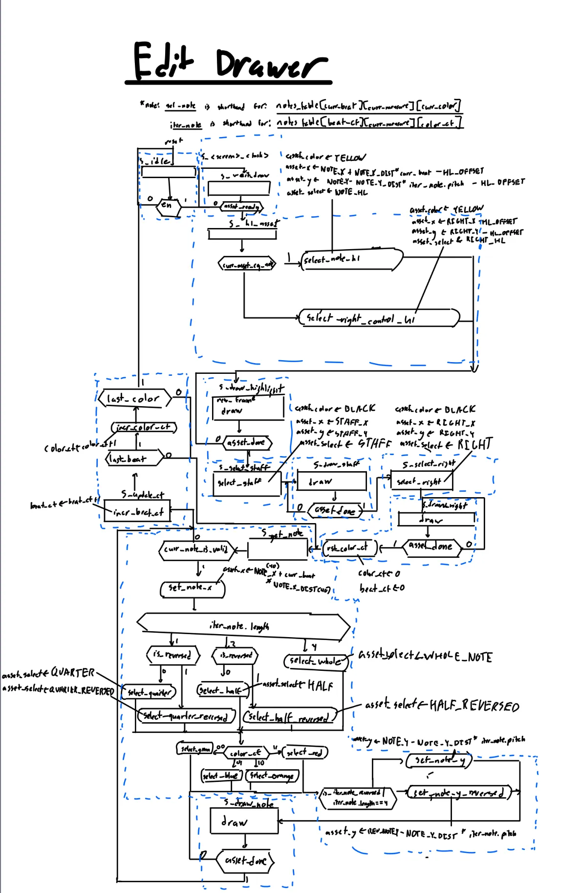
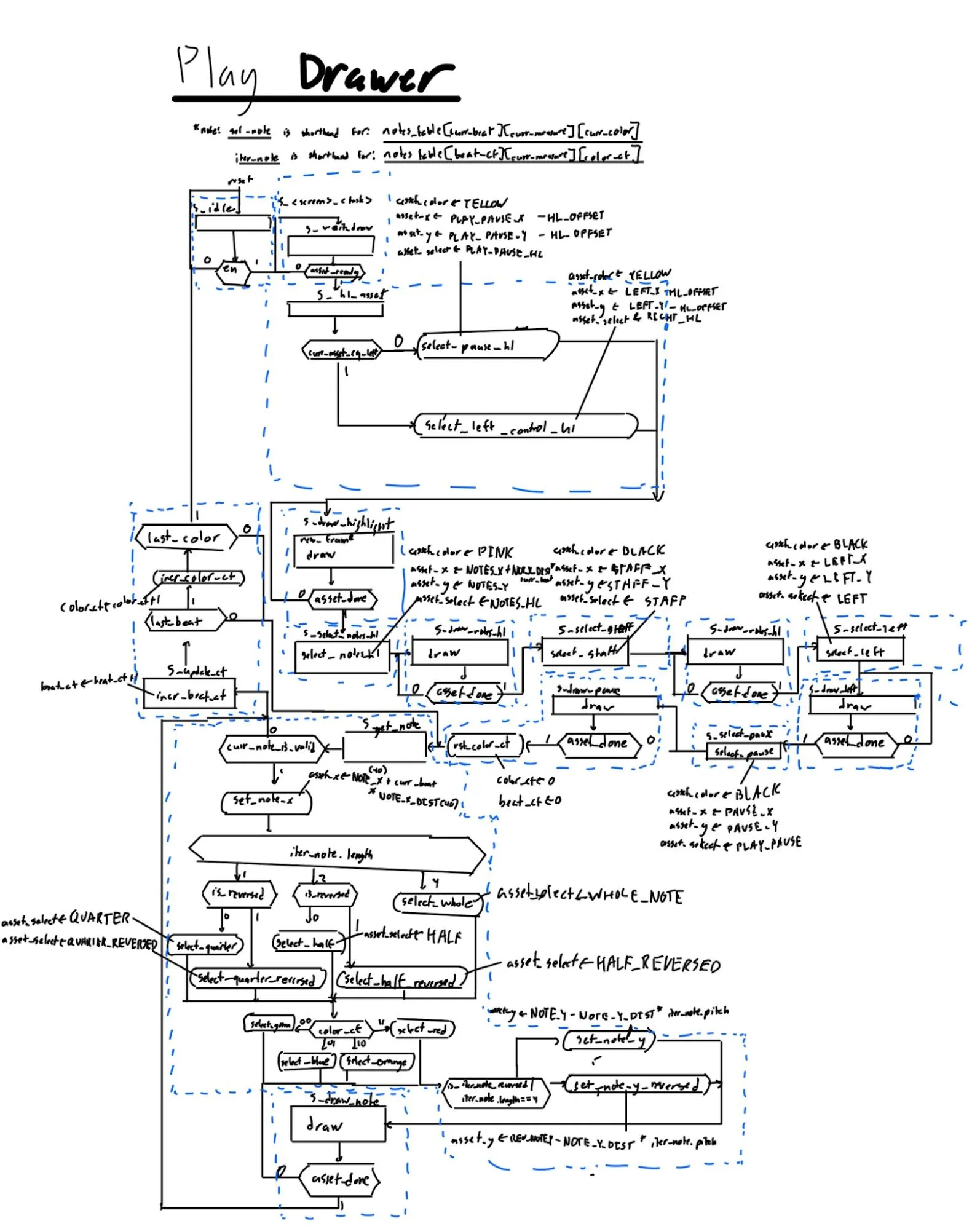 Figures 12 (left) and 13 (right): On the left is the edit drawer, and on the right is the play drawer. Note that the bottom portion that creates the different notes in the current measure is identical, as the logic is the same in both cases. The only difference is the other assets drawn onto the screen.
The edit_drawer and play_drawer FSMs draw static UI components sequentially (e.g., S_hl_asset → S_select_staff). They then enter a hardware loop to render the memory array. In S_get_note, the datapath fetches the current note. If curr_note_is_en is high, it enters S_draw_note. It then increments the counters in S_update_ct and loops back to S_get_note until all notes are evaluated.
Tune Drawer ASMD
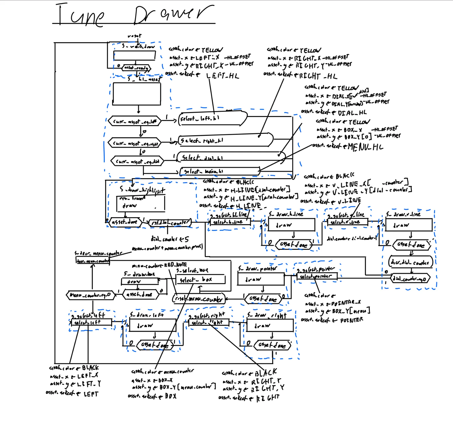 Figure 14: ASMD for the Tune Drawer. It is smaller because the outputs are used less dynamically while drawing, and it doesn’t require parsing data from a large map.
The tune_drawer draws dynamic settings and does not have the staff, so it is distinct. It loops 6 times to draw sliders (S_draw_h_line → S_draw_h_line → S_decr_counter) and a times to render the voice color palette (S_select_box → S_draw_box → S_decr_menu_counter).
Dynamic Sprite Calculation
To conserve ROM space, the datapath dynamically calculates note-stem orientation. If a note’s pitch is on or above the middle line of the treble clef (iter_note.pitch >= B4), the datapath selects the REVERSED asset enum and applies a mathematical offset to the Y-coordinate.
Parameterized Slider Mapping
The tune_drawer computes screen coordinates for slider knobs by performing a 2-bit right arithmetic shift on the 8-bit dial_table parameter (dial_table[dial_counter] >> 2), thereby scaling the volume parameter into a pixel offset.
UI Clocking and Coordination
The drawer_clock divides the system clock by 12.5, providing a stable time window for the rendering engine to complete its loops before the next frame is requested. The drawer_coordinator acts as a combinational multiplexer, routing signals only from the actively enabled drawer to prevent multiple-driver conflicts.
Task 7: N8 Input Buffer
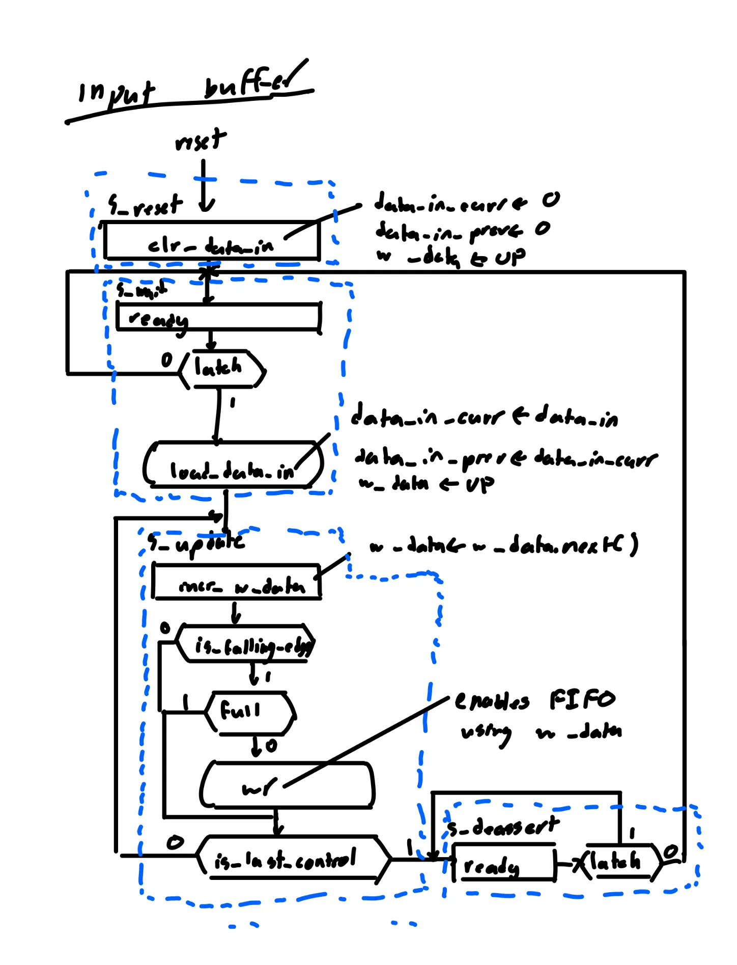 Figure 15: ASMD chart of the N8 input buffer control. The machine waits for a fresh latch signal, sequentially scans all 8 bits of the new data frame for falling edges, and pushes any newly pressed buttons into the FIFO queue before waiting for the next polling cycle.
The N8 Input Buffer processes controller input. To prevent single button presses from triggering redundant commands, we implemented an edge-detecting polling pipeline and a hardware FIFO.
Serial Driver
The serial_driver (provided by course staff) handles low-level communication with the controller shift register. By setting SPEED = 16, the state machine phases are stretched, allowing voltage stabilization before sampling.
Edge Detection and FIFO Queuing
The datapath implements a synchronous edge-detector. By comparing data_in_prev and data_in_curr, it identifies falling edges (~data_in_curr[w_data] & data_in_prev[w_data]). Detected button presses are pushed into a First-Word Fall-Through (FWFT) FIFO queue, allowing the system to process inputs sequentially.
State Machine and Algorithmic Flow
The FSM idles in S_wait until latch pulses. It transitions to S_update and steps through the 8 button states. If is_falling_edge is true, it asserts wr to push the input into the FIFO. Once it has evaluated all buttons, it transitions to S_deassert until the latch drops.
Task 8: Main Logic
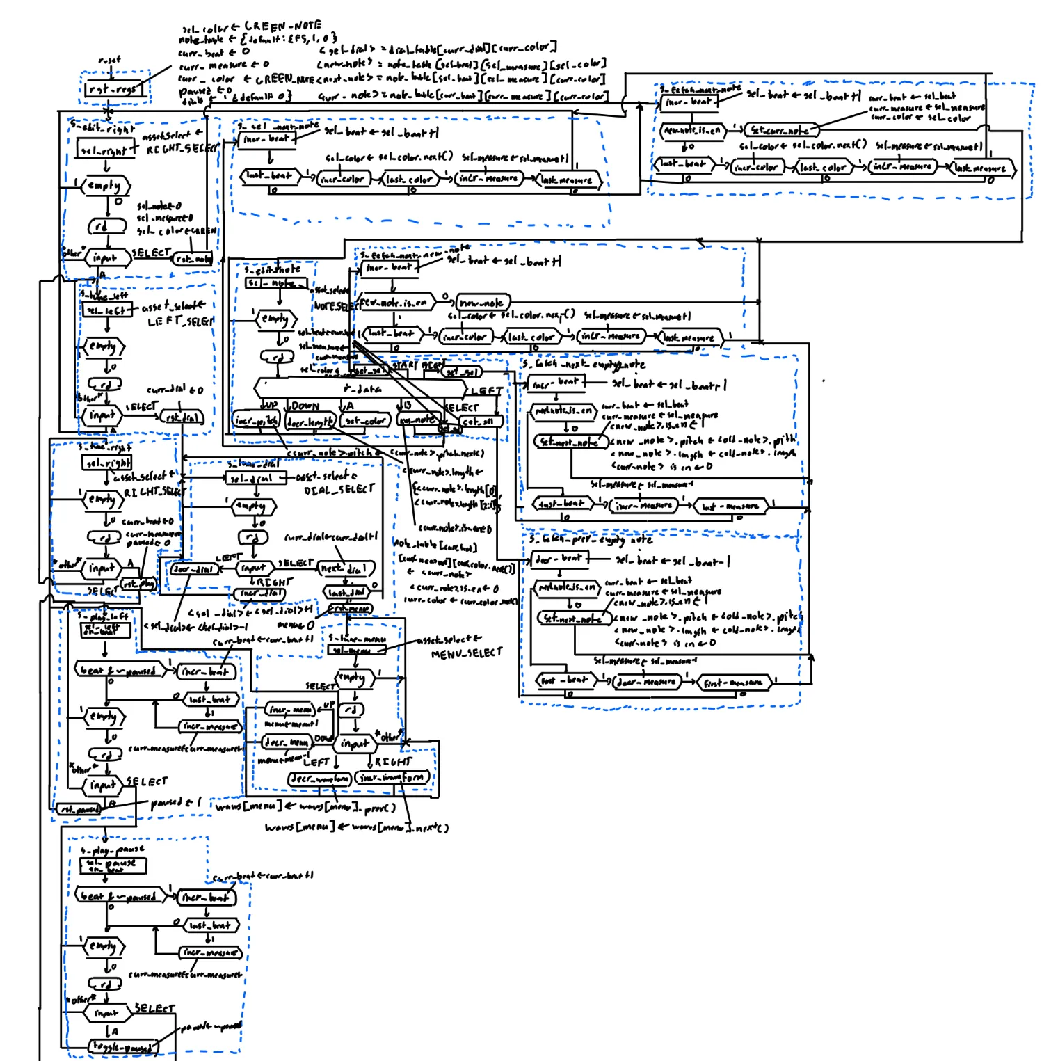 Figure 16: ASMD chart of the Main Logic Controller. The FSM polls the input FIFO to route navigation between Edit, Tune, and Play modes. It executes synchronous read-modify-write operations to update the 3D note array and manages a dual-pointer register system to decouple user UI navigation from the real-time audio playback coordinates.
The main_logic module coordinates data between the input_buffer, audio_controller, and UI drawers using an ASMD (Algorithmic State Machine with Datapath) architecture. It functions as the central router, mapping parsed hardware inputs to system-level state changes.
Routing and State Partitioning
The main_logic_control FSM utilizes 14 states partitioned into three primary modes: Edit, Tune, and Play. The present state (ps) acts as a logic guard, ensuring that controller inputs (r_data) trigger only context-appropriate operations. For instance, the datapath only evaluates pitch modification commands (incr_pitch) when the FSM is explicitly in the S_edit_note state, preventing unintended memory modifications during audio playback. The control block also outputs targeted active-high signals (use_edit, use_tune, use_play) to enable the corresponding UI drawer.
Register and Memory Synchronization
The main_logic_datapath manages the canonical note_table memory (a 3D array indexed by beat, measure, and color) using strictly synchronous read-modify-write operations. To prevent read conflicts between the UI and the audio hardware, the datapath implements a dual-pointer architecture. One set of internal registers (sel_beat, sel_measure, sel_color) tracks the user’s interface cursor. A separate set of output registers (curr_beat, curr_measure) tracks the active hardware playback position for the audio controller. This decoupling permits the user to navigate and modify notes in one measure while the audio hardware simultaneously reads from another.
State Machine and Algorithmic Flow
Upon initialization, the FSM defaults to S_edit_right. It continuously polls the input_buffer by evaluating the empty flag. When the FIFO contains data, the FSM consumes it by asserting rd. Inputting the SELECT_BUTTON triggers transitions through the primary UI modes (e.g., S_edit_right -> S_tune_left -> S_play_left).
During composition, the ASMD utilizes sequential look-ahead logic to manage the 3D array. If the user presses START_BUTTON while in S_edit_note, the FSM transitions to S_fetch_next_new_note. It iterates through the memory space, evaluating the new_note_is_en datapath flag to locate the next available array index. Once an empty slot is identified, the datapath populates it with a default note (F5 pitch, length 1), and the FSM returns to S_edit_note. Subsequent control inputs assert specific combinational signals (incr_pitch, decr_length, set_color, rm_note), directing the datapath to execute targeted, 1-clock-cycle synchronous updates to the selected note record.
Top-Level Integration
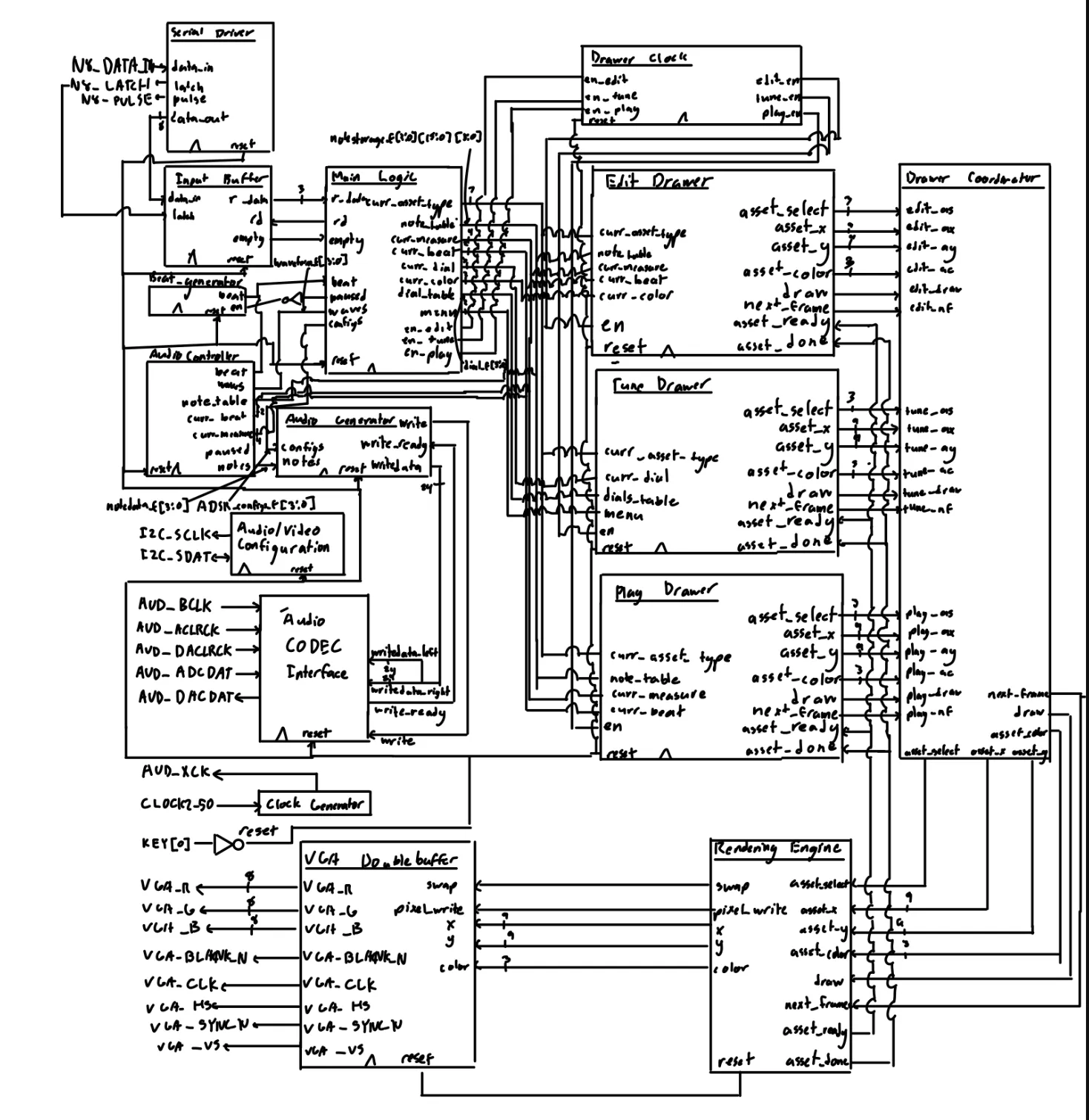 Figure 17: Top-level block diagram for the DE1_SoC. Note how the main logic is in the middle, and how all of its outputs are fed to the other modules.
The top-level wrapper instantiates the memory, audio generator, rendering engine, and main logic controller, bridging their data buses. Pixel outputs are routed to the VGA_framebuffer, and 24-bit audio samples are routed to the audio codec interface. Physical board buttons are inverted (assign reset = ~KEY[0]) for active-high reset logic.
Results
Overall, the project was a success. While using the board in LabsLand, users can use the N8 controller to move their selected highlighted box around the screen and use the large arrows to navigate between screens. In addition, they can perform all required tasks on all 3 screens. This includes the following:
Edit Screen
- Add/remove notes on the edit screen
- Change each note’s position, color, and length
- Preview all of the notes on the given measure
Tune Screen
- Edit where the dials are and tune the ADSR for each color
- Change the waveform while selecting the menus on the right
- Change which color’s ADSR you’re editing
Play Screen
- Watch the playhead move from beat to beat in a consistent manner
- Listen to the audio generated (including chords and different waveforms)
- Listen to the audio repeat back to the start
- Pause/play the audio
Unfortunately, there are some caveats. One such caveat is that inputs can be improperly latched if the SPEED on the serial_driver is too low. As such, if multiple controls are pressed at once with a single button press, the SPEED should be increased (I selected 16, as this was the fastest it could be without causing issues).
In addition, the audio output would occasionally not work. I believe this is an issue with LabsLand. As you will see in the demo, audio can be generated, but some of the boards do not seem to work. This is an ongoing issue, and I hope to resolve it while continuing to work on this project on the side.
Rendering Engine
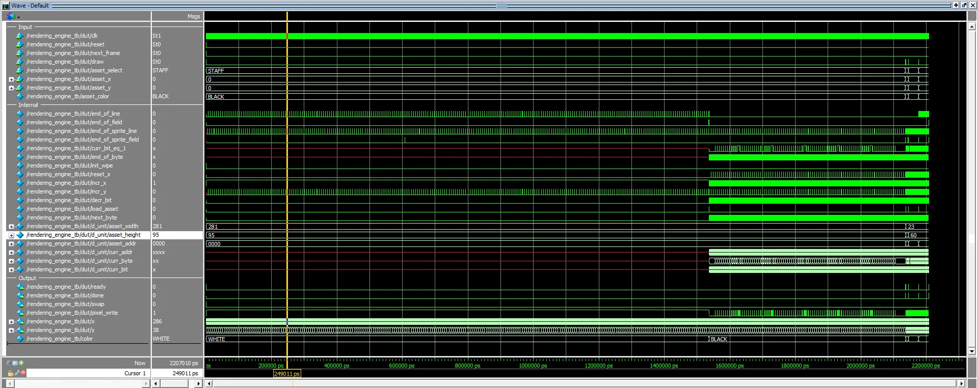 Figure 18: Overall waveform for the Rendering Engine module. Do note that most of the time in the waveform is spent erasing the prior front frame.
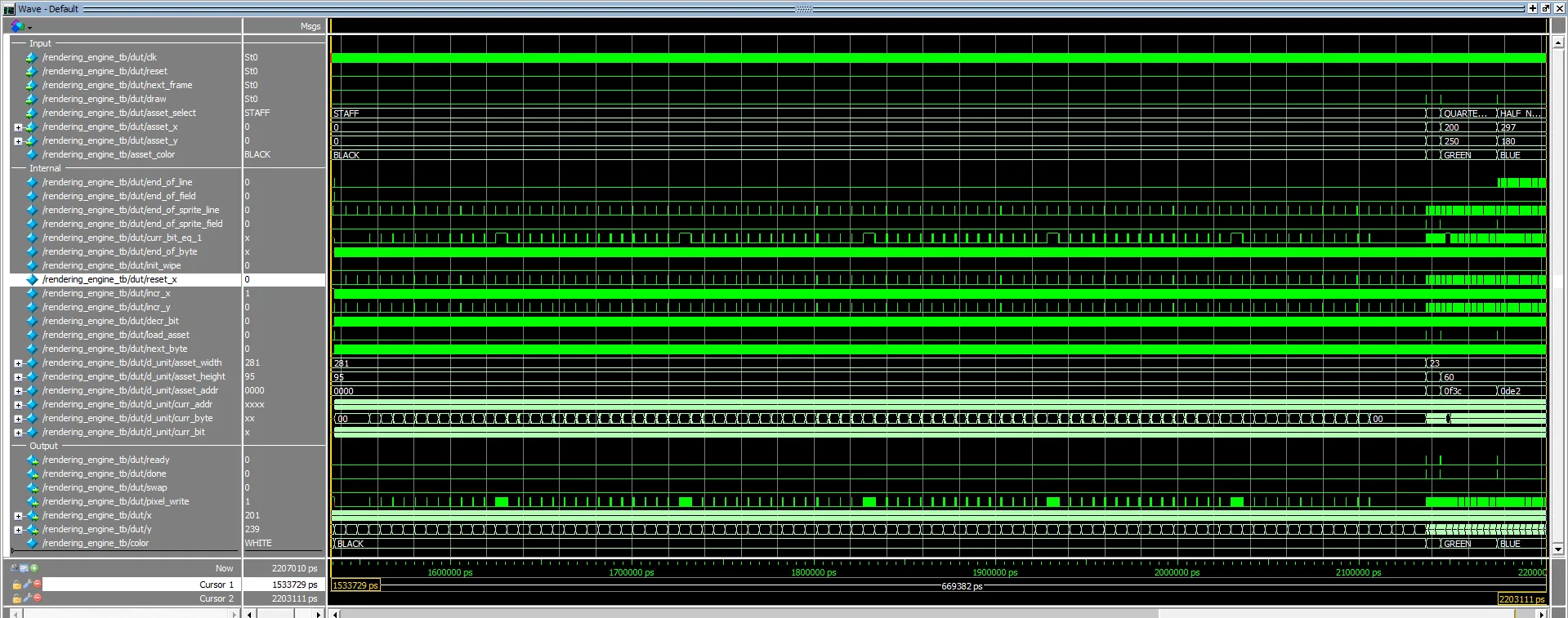 Figure 19: Zoomed-in waveform of the latter portion. Note how the pixel write is always asserted only when the current bit equals 1.
In this testbench, we verify the rendering_engine module, which processes high-level drawing commands and writes pixels sequentially to the VGA framebuffer. The primary goal was to verify the state machine’s ability to fetch appropriate pixel boundaries, iterate through dimensions, and correctly handle edge-case coordinate placements without overflowing the screen space.
Overall, the Rendering Engine consistently creates the requested asset. During Test Case 1, the module successfully processes the STAFF asset at the origin (0, 0). In subsequent tests, it precisely places other assets, including a WHOLE_NOTE at (150, 150) and a QUARTER_NOTE_REVERSED at (200, 250). Notably, the output y changes at a fairly consistent, slow interval, while x changes every clock cycle, forming a scanning pattern that reflects the asset’s size.
VGA Dual Buffer
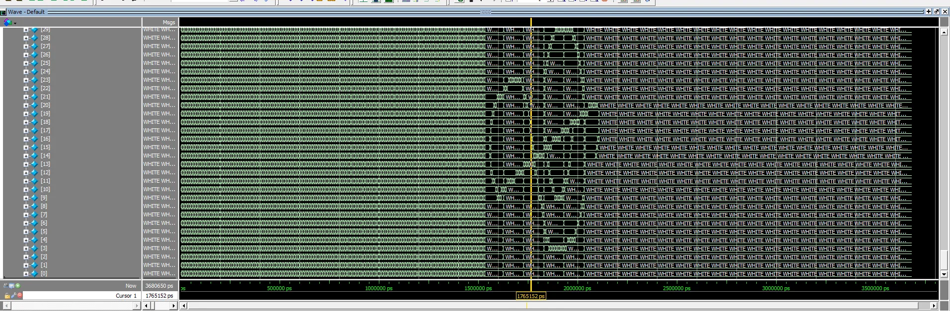 Figure 20: We see the rendering engine scan through the framebuffer and change some value in the column for framebuffer 0. As a result, we see a 90-degree-rotated version of a treble clef, with the staff lines radiating outward.
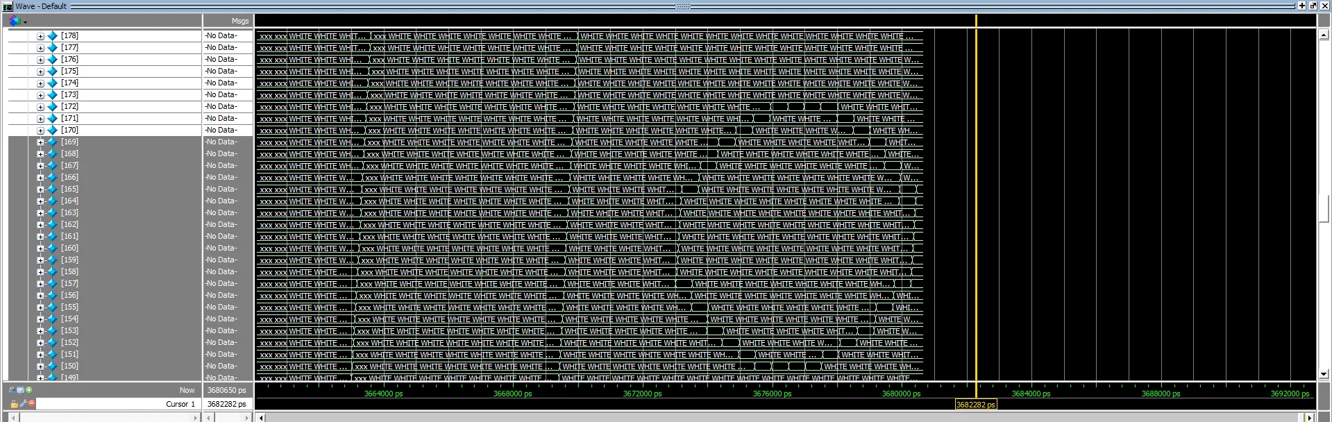 Figure 21: We see the rendering engine scan through the framebuffer and only change values in framebuffer 1. As a result, we see a 90-degree-rotated version of the whole note that was encoded during this time interval.
In this testbench, we verify the VGA_dual_buffer module by confirming its ability to route high-speed pixel writes to alternating memory blocks. The primary goal was to ensure absolute read/write isolation between the rendering engine and the physical VGA driver, proving that the foreground image remains perfectly stable. At the same time, the background frame is being actively composed.
During the first testing phase, we observe the rendering engine scanning through the memory space and executing pixel writes exclusively to framebuffer 0. As the 1D memory array is populated, the resulting data forms a treble clef with radiating staff lines. Notably, the asset appears rotated 90 degrees in the memory viewer. This is an expected artifact of our 1D array flattening calculation (driver_x + (driver_y<<8) + (driver_y<<6)); because the engine’s X/Y coordinate iteration (column-major) is transposed relative to the physical monitor’s horizontal scanlines (row-major), the raw memory appears rotated. However, it maps perfectly to the correct upright orientations on the physical VGA hardware.
In the subsequent testing phase, the swap signal is toggled, and we observe the rendering engine’s write operations cleanly switch over to framebuffer 1. During this time interval, the engine modifies only the values in this alternate memory block, successfully encoding a 90-degree-rotated version of the whole-note asset. Crucially, the waveform proves that while framebuffer 1 is being actively manipulated by the rendering engine, the data in framebuffer 0 remains completely locked and undisturbed. This confirms our double-buffered architecture is flawless: the physical monitor can safely read the static treble clef from buffer 0 without any visual tearing, while the engine simultaneously composes the whole note out of sight in buffer 1.
ADSR Envelope
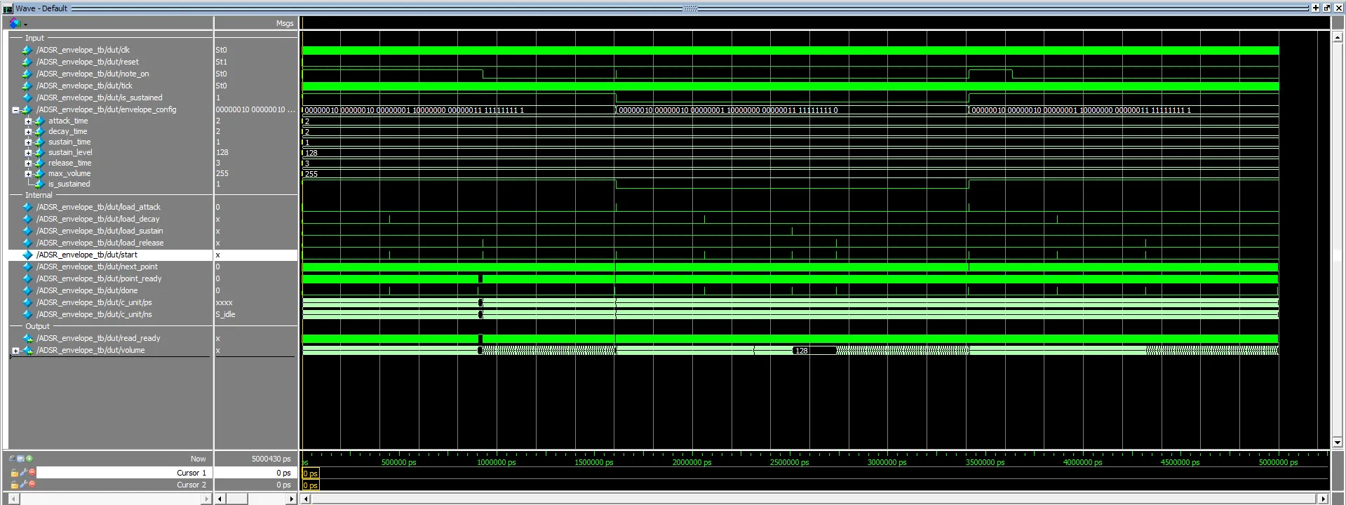 Figure 22: Overall waveform for the ADSR envelope, with note_on going high at 3 difference instances.
# [1330] Volume changed: 1
# [3090] Volume changed: 2
# [4850] Volume changed: 3
# [6610] Volume changed: 4
# [8370] Volume changed: 5
# [10130] Volume changed: 6
Figure 23: While in the initial attack phase, the timing between volume changes is consistent (1760 ps).
# [448150] Volume changed: 254
# [449910] Volume changed: 255
# [452770] Volume changed: 254
# [456290] Volume changed: 253
# [459810] Volume changed: 252
# [463330] Volume changed: 251
# [466850] Volume changed: 250
Figure 24: In transitioning from attack to decay, the timing between volume changes is slower (3520 ps)
# [896070] Volume changed: 129
# [899590] Volume changed: 128
# [929090] Volume changed: 127
...
# [1589090] Volume changed: 2
# [1594370] Volume changed: 1
# [1599650] Volume changed: 0
Figure 25: Once reaching the sustain threshold of 128, the time until the release stage increases to 29500 ps, and releases steadily every 5280 ps.
In this testbench, we verify the ADSR_envelope module by simulating the four distinct phases of note articulation (Attack, Decay, Sustain, and Release). The primary goal was to ensure that the Bresenham line-drawer math correctly translates parameterized durations and levels into a fluid 8-bit volume multiplier.
From 1330 ps to 10130 ps, we observe the initial Attack phase. Triggered by the note_on signal, the datapath consistently increments the volume towards the maximum limit of 255. The testbench registers a highly consistent delta of 1760 ps between volume changes, confirming a perfectly linear slope.
As the volume approaches the peak at 448150 ps, the envelope successfully transitions into the Decay phase. At this point, the module targets the parameterized sustain_level of 128. We observe the timing delta widen to 3520 ps between ticks (e.g., from 452770 ps to 456290 ps) as the engine correctly recalculates the slope for a more gradual fade.
Once the volume successfully decays to the 128 threshold at 899590 ps, the envelope enters the Sustain phase. Because the testbench asserts is_sustained = 1, the module perfectly holds this volume level indefinitely. Finally, when note_on is dropped, the module enters the Release phase (beginning at 1589090 ps). The time between volume decrements increases drastically to 5280 ps, ensuring a smooth, natural fade-out to absolute silence (0).
Audio Generator
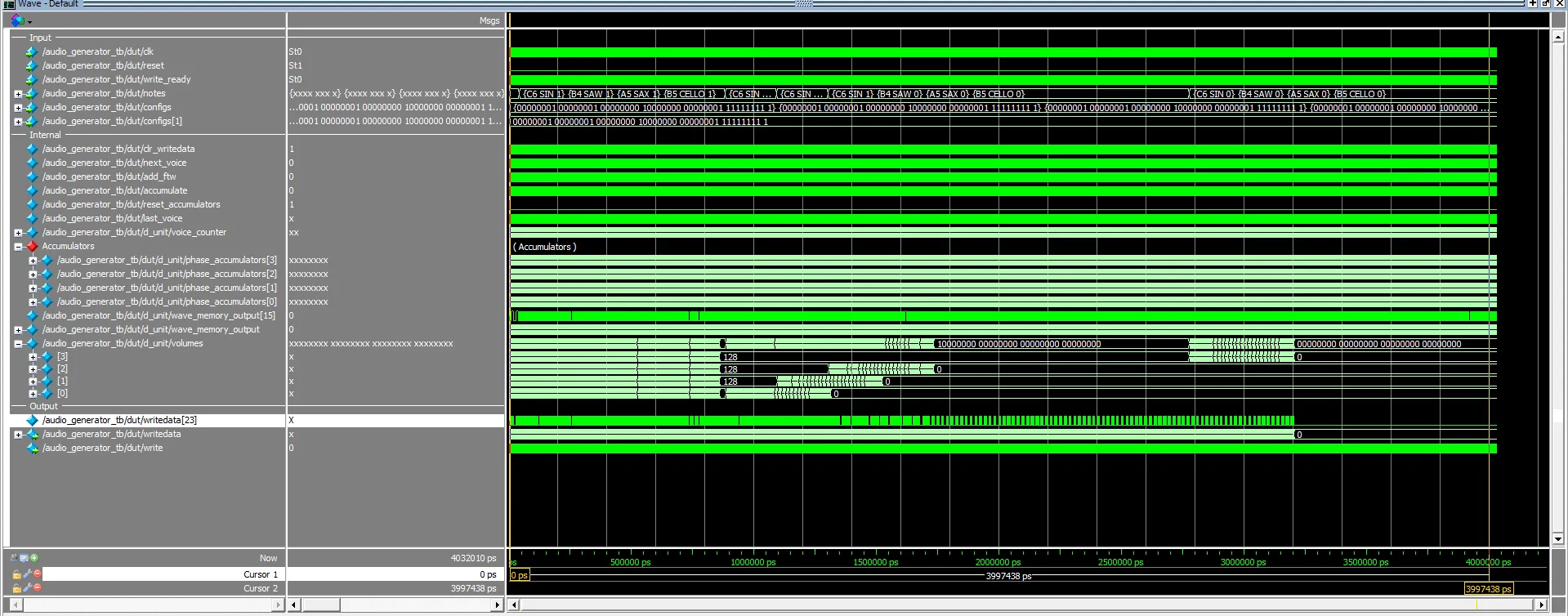 Figure 26: Overall testbench for the Audio Generator.
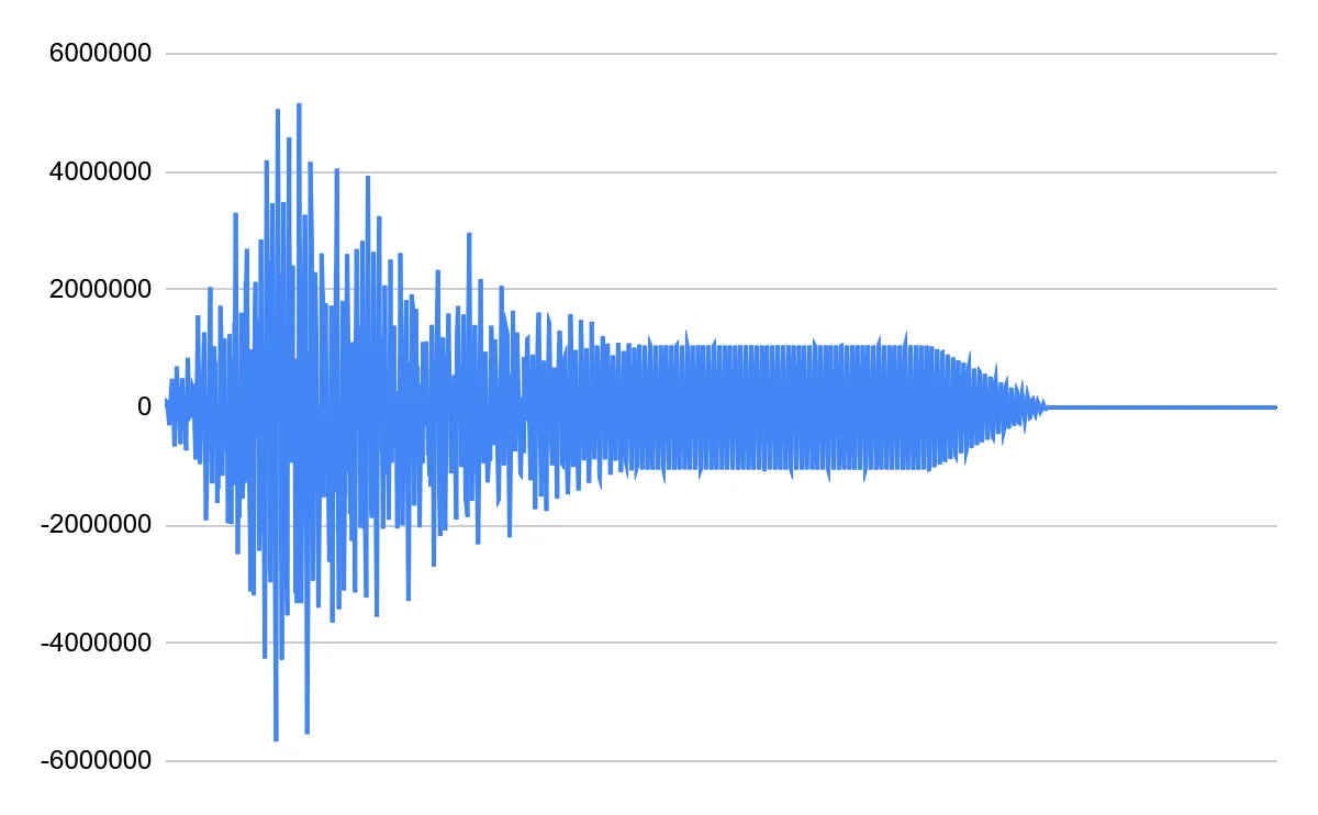 Figure 27: Every sample from the audio generator is laid out in a chart. Note that there’s a clear ADSR behavior of an increase to the max value for attack before decreasing to a sustained value, and then completely dropping off.
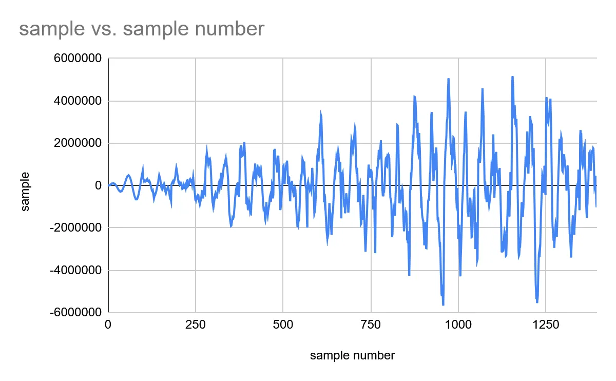 Figure 28: Samples from the beginning of the generator. Note the generator increasing in amplitude due to the attack phase of the ADSR. Also note the shift from the first 2 smooth sine waves, where all the voices are the same, to a more jagged waveform after superimposing the different voices, which have jagged waveforms of their own.
In this testbench, we verify the audio_generator by analyzing the discrete DSP output samples sent to the CODEC. The goal was to confirm that the direct digital synthesis (DDS) phase accumulators operate correctly across multiple frequencies and that the hardware multiplier safely mixes polyphonic waveforms.
Upon observing the sample output, there is a clear ADSR behavior shaping the amplitude of the raw waveforms, proving that the integration between the ADSR_envelope array and the audio_generator is flawless. Early in the simulation, we observe clean, smooth sine waves as the SIN enum is passed to the active voices. As the testbench transitions into evaluating CELLO, SAX, and SAW enums simultaneously, the output shifts from a smooth curve to a highly complex, jagged waveform. This visually confirms that the module is successfully superimposing and mixes four distinct, mathematically complex timbres in real time without exceeding the signed 24-bit integer limit.
Audio Controller
 Figure 29: Overall waveform of the Audio Controller.
This testbench effectively shows how notes of different lengths, each in a different color, act independently and last for the appropriate duration across the waveform. We start with the A5 with a SQUARE waveform of length 1 from the beginning, which lasts half of the time until the next beat, showing that the notes do release when they are length 1. Similarly, at the start of beat 2, B5, with a TRIANGLE waveform and a length of 2, is enabled. However, it is interrupted with a pause, and thus the is_on part of notedata_t is set to low. Even so, the note immediately starts back up after being paused, and even lasts the 1.5 beats that it ought to due to the length of 2.
Drawers
Edit Drawer
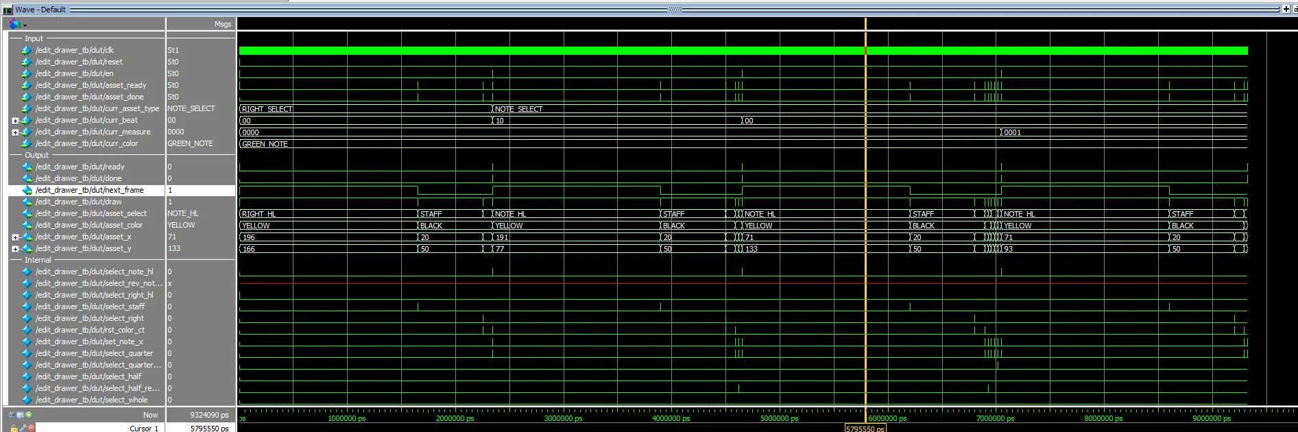 Figure 30: Overall waveform of the Edit Drawer testbench.
Starting Test 1: Empty Measure
# [130] Engine Received draw command
#       Asset: RIGHT_HL, Color: YELLOW, Coord: (196, 166)
# [1652850] Engine Received draw command
#       Asset: STAFF, Color: BLACK, Coord: (20, 50)
# [2253570] Engine Received draw command
#       Asset: RIGHT, Color: BLACK, Coord: (200, 170)
# Finished Test 1
# Starting Test 2: Melody
# [2344330] Engine Received draw command
#       Asset: NOTE_HL, Color: YELLOW, Coord: (191, 77)
# [3896470] Engine Received draw command
#       Asset: STAFF, Color: BLACK, Coord: (20, 50)
# [4497190] Engine Received draw command
#       Asset: RIGHT, Color: BLACK, Coord: (200, 170)
# [4587270] Engine Received draw command
#       Asset: QUARTER_NOTE, Color: GREEN, Coord: (75, 92)
# [4618470] Engine Received draw command
#       Asset: HALF_NOTE_REVERSED, Color: GREEN, Coord: (195, 81)
# Finished Test 2
# Starting Test 3: Four Voices
# [4650190] Engine Received draw command
#       Asset: NOTE_HL, Color: YELLOW, Coord: (71, 133)
# [6202330] Engine Received draw command
#       Asset: STAFF, Color: BLACK, Coord: (20, 50)
# [6803050] Engine Received draw command
#       Asset: RIGHT, Color: BLACK, Coord: (200, 170)
# [6893130] Engine Received draw command
#       Asset: QUARTER_NOTE, Color: GREEN, Coord: (75, 92)
# [6924330] Engine Received draw command
#       Asset: HALF_NOTE_REVERSED, Color: GREEN, Coord: (195, 81)
# [6955530] Engine Received draw command
#       Asset: QUARTER_NOTE, Color: BLUE, Coord: (75, 76)
# [6986810] Engine Received draw command
#       Asset: QUARTER_NOTE, Color: ORANGE, Coord: (75, 60)
# [7018090] Engine Received draw command
#       Asset: QUARTER_NOTE_REVERSED, Color: RED, Coord: (75, 81)
# Finished Test 3
# Starting Test 4: Pagination
# [7049410] Engine Received draw command
#       Asset: NOTE_HL, Color: YELLOW, Coord: (71, 93)
# [8601550] Engine Received draw command
#       Asset: STAFF, Color: BLACK, Coord: (20, 50)
# [9202270] Engine Received draw command
#       Asset: RIGHT, Color: BLACK, Coord: (200, 170)
# [9292350] Engine Received draw command
#       Asset: QUARTER_NOTE, Color: GREEN, Coord: (75, 52)
# Finished Test 4
Figure 31: Display output from the testbench every time that draw has a rising edge. Thus, the rendering engine is drawing only exactly what we are requesting from the edit drawer.
In this testbench, we verify the edit_drawer module by confirming its ability to dynamically iterate over the 3D memory array and issue correct sequential rendering commands to the VGA engine based on the composition state.
During Test 1 (Empty Measure), from 130 ps to 2253570 ps, the FSM flawlessly draws the static background components. It first issues the command for the yellow cursor highlight at (196, 166), followed by the staff lines and the right navigation button, and correctly halts and asserts done because the note memory is empty.
In Test 2 (Melody) and Test 3 (Four Voices), we populate the memory with active notes. Starting at 4587270 ps, the FSM successfully discovers an active note and directs the engine to draw a green QUARTER_NOTE at (75, 92). Immediately after, the datapath dynamically calculates that the C5 pitch exceeds the staff midpoint, correctly appending the _REVERSED property to the half note and shifting its Y-coordinate to 81. In Test 3, from 6893130 ps to 7018090 ps, the engine seamlessly stacks a four-note chord on a single beat, demonstrating that the nested color-iteration loop successfully offsets the coordinates without overlap.
Tune Drawer
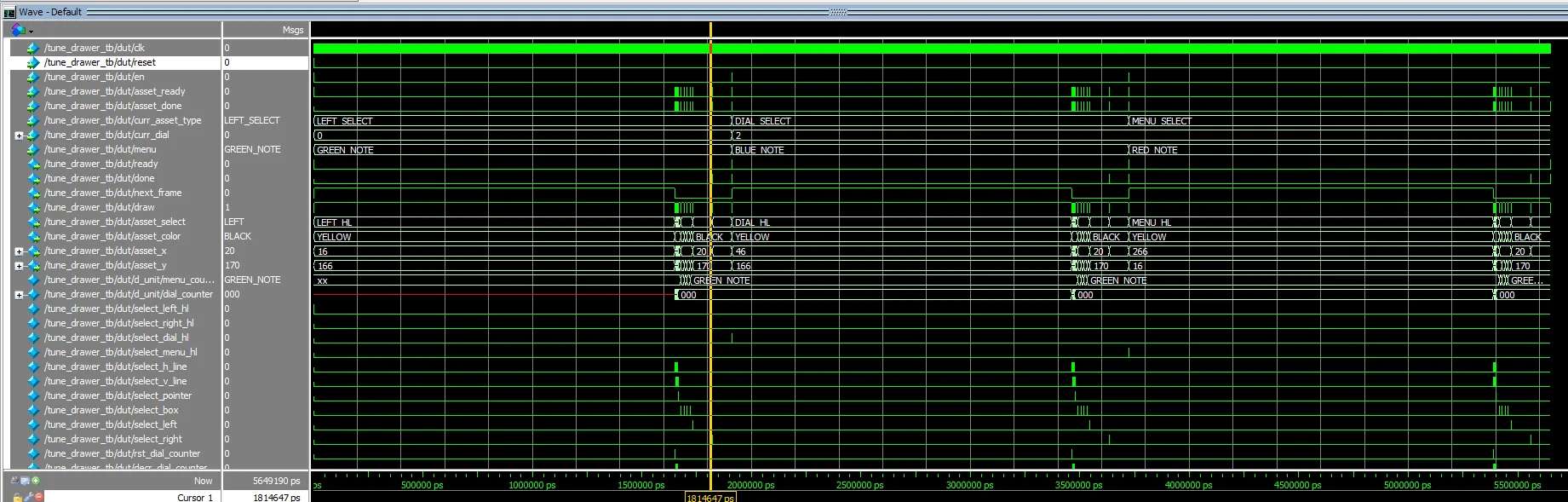 Figure 32: Overall waveform of the Tune Drawer testbench.
# Starting Test 1: Left Highlight & Default Pointer
# [130] Engine Received draw command
#       Asset: LEFT_HL, Color: YELLOW, Coord: (16, 166)
# [1652850] Engine Received draw command
#       Asset: H_LINE, Color: BLACK, Coord: (150, 170)
# [1654550] Engine Received draw command
#       Asset: V_LINE, Color: BLACK, Coord: (204, 165)
# [1654910] Engine Received draw command
#       Asset: H_LINE, Color: BLACK, Coord: (150, 110)
# [1656610] Engine Received draw command
#       Asset: V_LINE, Color: BLACK, Coord: (194, 105)
# [1656970] Engine Received draw command
#       Asset: H_LINE, Color: BLACK, Coord: (150, 50)
# [1658670] Engine Received draw command
#       Asset: V_LINE, Color: BLACK, Coord: (174, 45)
# [1659030] Engine Received draw command
#       Asset: H_LINE, Color: BLACK, Coord: (50, 170)
# [1660730] Engine Received draw command
#       Asset: V_LINE, Color: BLACK, Coord: (64, 165)
# [1661090] Engine Received draw command
#       Asset: H_LINE, Color: BLACK, Coord: (50, 110)
# [1662790] Engine Received draw command
#       Asset: V_LINE, Color: BLACK, Coord: (59, 105)
# [1663150] Engine Received draw command
#       Asset: H_LINE, Color: BLACK, Coord: (50, 50)
# [1664850] Engine Received draw command
#       Asset: V_LINE, Color: BLACK, Coord: (56, 45)
# [1665190] Engine Received draw command
#       Asset: POINTER, Color: BLACK, Coord: (230, 20)
# [1678770] Engine Received draw command
#       Asset: BOX, Color: RED, Coord: (270, 140)
# [1692370] Engine Received draw command
#       Asset: BOX, Color: ORANGE, Coord: (270, 100)
# [1705970] Engine Received draw command
#       Asset: BOX, Color: BLUE, Coord: (270, 60)
# [1719570] Engine Received draw command
#       Asset: BOX, Color: GREEN, Coord: (270, 20)
# [1733150] Engine Received draw command
#       Asset: LEFT, Color: BLACK, Coord: (20, 170)
# [1823230] Engine Received draw command
#       Asset: RIGHT, Color: BLACK, Coord: (200, 170)
# Finished Test 1
#
# Starting Test 2: Dial Highlight & Blue Pointer
# [1913350] Engine Received draw command
#       Asset: DIAL_HL, Color: YELLOW, Coord: (46, 166)
# [3465630] Engine Received draw command
#       Asset: H_LINE, Color: BLACK, Coord: (150, 170)
# [3467330] Engine Received draw command
#       Asset: V_LINE, Color: BLACK, Coord: (204, 165)
# [3467690] Engine Received draw command
#       Asset: H_LINE, Color: BLACK, Coord: (150, 110)
# [3469390] Engine Received draw command
#       Asset: V_LINE, Color: BLACK, Coord: (194, 105)
# [3469750] Engine Received draw command
#       Asset: H_LINE, Color: BLACK, Coord: (150, 50)
# [3471450] Engine Received draw command
#       Asset: V_LINE, Color: BLACK, Coord: (174, 45)
# [3471810] Engine Received draw command
#       Asset: H_LINE, Color: BLACK, Coord: (50, 170)
# [3473510] Engine Received draw command
#       Asset: V_LINE, Color: BLACK, Coord: (64, 165)
# [3473870] Engine Received draw command
#       Asset: H_LINE, Color: BLACK, Coord: (50, 110)
# [3475570] Engine Received draw command
#       Asset: V_LINE, Color: BLACK, Coord: (59, 105)
# [3475930] Engine Received draw command
#       Asset: H_LINE, Color: BLACK, Coord: (50, 50)
# [3477630] Engine Received draw command
#       Asset: V_LINE, Color: BLACK, Coord: (56, 45)
# [3477970] Engine Received draw command
#       Asset: POINTER, Color: BLACK, Coord: (230, 60)
# [3491550] Engine Received draw command
#       Asset: BOX, Color: RED, Coord: (270, 140)
# [3505150] Engine Received draw command
#       Asset: BOX, Color: ORANGE, Coord: (270, 100)
# [3518750] Engine Received draw command
#       Asset: BOX, Color: BLUE, Coord: (270, 60)
# [3532350] Engine Received draw command
#       Asset: BOX, Color: GREEN, Coord: (270, 20)
# [3545930] Engine Received draw command
#       Asset: LEFT, Color: BLACK, Coord: (20, 170)
# [3636010] Engine Received draw command
#       Asset: RIGHT, Color: BLACK, Coord: (200, 170)
# Finished Test 2
#
# Starting Test 3: Menu Highlight & Red Pointer
# [3726130] Engine Received draw command
#       Asset: MENU_HL, Color: YELLOW, Coord: (266, 16)
# [5388750] Engine Received draw command
#       Asset: H_LINE, Color: BLACK, Coord: (150, 170)
# [5390450] Engine Received draw command
#       Asset: V_LINE, Color: BLACK, Coord: (204, 165)
# [5390810] Engine Received draw command
#       Asset: H_LINE, Color: BLACK, Coord: (150, 110)
# [5392510] Engine Received draw command
#       Asset: V_LINE, Color: BLACK, Coord: (194, 105)
# [5392870] Engine Received draw command
#       Asset: H_LINE, Color: BLACK, Coord: (150, 50)
# [5394570] Engine Received draw command
#       Asset: V_LINE, Color: BLACK, Coord: (174, 45)
# [5394930] Engine Received draw command
#       Asset: H_LINE, Color: BLACK, Coord: (50, 170)
# [5396630] Engine Received draw command
#       Asset: V_LINE, Color: BLACK, Coord: (64, 165)
# [5396990] Engine Received draw command
#       Asset: H_LINE, Color: BLACK, Coord: (50, 110)
# [5398690] Engine Received draw command
#       Asset: V_LINE, Color: BLACK, Coord: (59, 105)
# [5399050] Engine Received draw command
#       Asset: H_LINE, Color: BLACK, Coord: (50, 50)
# [5400750] Engine Received draw command
#       Asset: V_LINE, Color: BLACK, Coord: (56, 45)
# [5401090] Engine Received draw command
#       Asset: POINTER, Color: BLACK, Coord: (230, 140)
# [5414670] Engine Received draw command
#       Asset: BOX, Color: RED, Coord: (270, 140)
# [5428270] Engine Received draw command
#       Asset: BOX, Color: ORANGE, Coord: (270, 100)
# [5441870] Engine Received draw command
#       Asset: BOX, Color: BLUE, Coord: (270, 60)
# [5455470] Engine Received draw command
#       Asset: BOX, Color: GREEN, Coord: (270, 20)
# [5469050] Engine Received draw command
#       Asset: LEFT, Color: BLACK, Coord: (20, 170)
# [5559130] Engine Received draw command
#       Asset: RIGHT, Color: BLACK, Coord: (200, 170)
# Finished Test 3
Figure 33: Transcript of what is happening in the Tune Drawer testbench.
In this testbench, we verify that tune_drawer properly generates the dynamic sliders and color menus based on the live 8-bit dial_table configurations.
In Test 1, from 130 ps to 1823230 ps, the drawer initializes the default tuning UI. We observe the FSM executing its 6-iteration slider loop (alternating H_LINE and V_LINE), successfully mapping the horizontal lines at fixed intervals (X=150, 50, etc.) and shifting the vertical slider indicators according to the provided mock data.
During Test 2 (Dial Highlight & Blue Pointer), beginning at 1913350 ps, the datapath proves it can dynamically highlight the correct dial element. The engine successfully draws DIAL_HL at (46, 166). Furthermore, as the menu state changes, the POINTER asset correctly shifts its Y-coordinate from 20 down to 60 at 3477970 ps.
Play Drawer
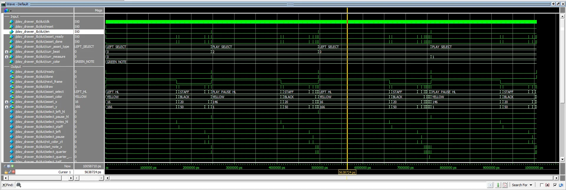 Figure 34: Overall waveform of the Play Drawer testbench.
# Starting Test 1: Empty Measure
# [130] Engine Received draw command
#       Asset: LEFT_HL, Color: YELLOW, Coord: (16, 166)
# [1652850] Engine Received draw command
#       Asset: NOTES_HL, Color: PINK, Coord: (73, 55)
# [1711670] Engine Received draw command
#       Asset: STAFF, Color: BLACK, Coord: (20, 50)
# [2312390] Engine Received draw command
#       Asset: LEFT, Color: BLACK, Coord: (20, 170)
# [2402470] Engine Received draw command
#       Asset: PLAY_PAUSE, Color: BLACK, Coord: (150, 5)
# Finished Test 1
#
# Starting Test 2: Melody
# [2468030] Engine Received draw command
#       Asset: PLAY_PAUSE_HL, Color: YELLOW, Coord: (146, 1)
# [4089790] Engine Received draw command
#       Asset: NOTES_HL, Color: PINK, Coord: (193, 55)
# [4148610] Engine Received draw command
#       Asset: STAFF, Color: BLACK, Coord: (20, 50)
# [4749330] Engine Received draw command
#       Asset: LEFT, Color: BLACK, Coord: (20, 170)
# [4839410] Engine Received draw command
#       Asset: PLAY_PAUSE, Color: BLACK, Coord: (150, 5)
# [4904290] Engine Received draw command
#       Asset: QUARTER_NOTE, Color: GREEN, Coord: (75, 92)
# [4935490] Engine Received draw command
#       Asset: HALF_NOTE_REVERSED, Color: GREEN, Coord: (195, 81)
# Finished Test 2
#
# Starting Test 3: Four Voices
# [4967210] Engine Received draw command
#       Asset: LEFT_HL, Color: YELLOW, Coord: (16, 166)
# [6619930] Engine Received draw command
#       Asset: NOTES_HL, Color: PINK, Coord: (73, 55)
# [6678750] Engine Received draw command
#       Asset: STAFF, Color: BLACK, Coord: (20, 50)
# [7279470] Engine Received draw command
#       Asset: LEFT, Color: BLACK, Coord: (20, 170)
# [7369550] Engine Received draw command
#       Asset: PLAY_PAUSE, Color: BLACK, Coord: (150, 5)
# [7434430] Engine Received draw command
#       Asset: QUARTER_NOTE, Color: GREEN, Coord: (75, 92)
# [7465630] Engine Received draw command
#       Asset: HALF_NOTE_REVERSED, Color: GREEN, Coord: (195, 81)
# [7496830] Engine Received draw command
#       Asset: QUARTER_NOTE, Color: BLUE, Coord: (75, 76)
# [7528110] Engine Received draw command
#       Asset: QUARTER_NOTE, Color: ORANGE, Coord: (75, 60)
# [7559390] Engine Received draw command
#       Asset: QUARTER_NOTE_REVERSED, Color: RED, Coord: (75, 81)
# Finished Test 3
#
# Starting Test 4: Pagination
# [7590710] Engine Received draw command
#       Asset: PLAY_PAUSE_HL, Color: YELLOW, Coord: (146, 1)
# [9212470] Engine Received draw command
#       Asset: NOTES_HL, Color: PINK, Coord: (73, 55)
# [9271290] Engine Received draw command
#       Asset: STAFF, Color: BLACK, Coord: (20, 50)
# [9872010] Engine Received draw command
#       Asset: LEFT, Color: BLACK, Coord: (20, 170)
# [9962090] Engine Received draw command
#       Asset: PLAY_PAUSE, Color: BLACK, Coord: (150, 5)
# [10026970] Engine Received draw command
#       Asset: QUARTER_NOTE, Color: GREEN, Coord: (75, 52)
# Finished Test 4
Figure 35: Transcript of what is happening in the Play Drawer testbench
In this testbench, we verify the play_drawer module by confirming that it correctly prioritizes playback-specific UI elements (such as the Play/Pause button) over editing tools.
From 130 ps to 2402470 ps (Test 1), the FSM correctly initializes the Play mode backdrop. It successfully replaces the standard note highlights with the global NOTES_HL asset (the pink playback scanner) at (73, 55), and replaces the right navigation arrow with the PLAY_PAUSE toggle asset at (150, 5). As we progress to Test 2 (2468030 ps) and modify the selection cursor, the FSM successfully processes the PLAY_PAUSE_HL selection, rendering a yellow highlight at (146, 1) to indicate the user is hovering over the playback controls.
N8 Input Buffer
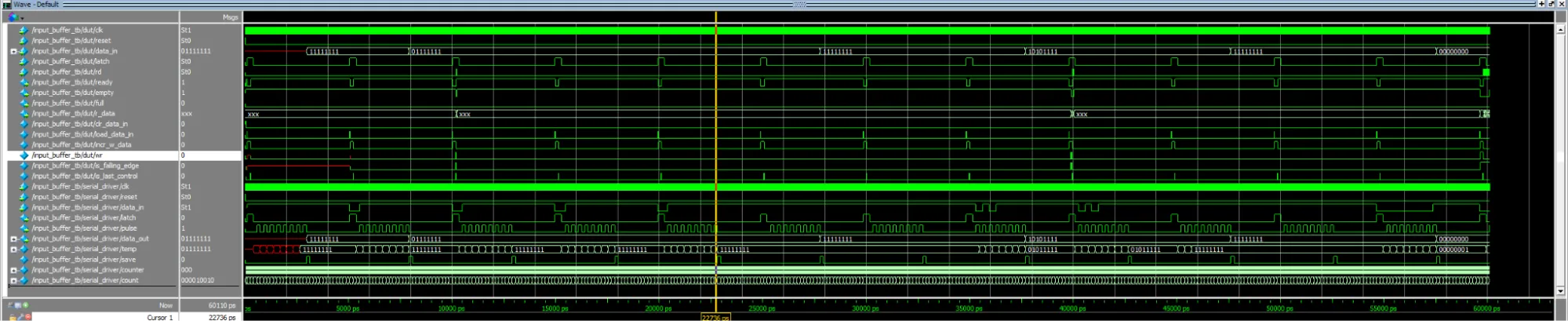 Figure 36:Overall waveform of the input buffer testbench (which also tests the serial driver).
# --- Test Case 1: Single Press ---
# [10210] FIFO Read: START
# --- Test Case 2: Hold Button ---
# [20110] FIFO is empty, nothing to read.
# --- Test Case 3: Release Button ---
# [30030] FIFO is empty, nothing to read.
# --- Test Case 4: Multi-Press ---
# [39970] FIFO Read: A
# [40010] FIFO Read: SELECT
# --- Test Case 5: Button Mash ---
# [59810] FIFO Read: UP
# [59850] FIFO Read: DOWN
# [59890] FIFO Read: LEFT
# [59930] FIFO Read: RIGHT
# [59970] FIFO Read: A
# [60010] FIFO Read: B
# [60050] FIFO Read: SELECT
# [60090] FIFO Read: START
Figure 37: Transcript from the input buffer testbench
In this testbench, we verify the input_buffer module alongside the serial_driver to ensure physical button presses are correctly debounced, edge-detected, and pushed into the FWFT FIFO queue.
In Test Case 1, the mock hardware provides a standard START button press. At 10210 ps, the input_buffer perfectly isolates the falling edge and pushes START to the FIFO. During Test Case 2 (20110 ps), the button is intentionally held down. The datapath correctly recognizes this as a steady state rather than a new edge, leaving the FIFO empty and preventing unwanted rapid-fire inputs. Releasing the button in Test Case 3 similarly produces no unintended reads.
The system’s robustness is fully proven in Test Cases 4 and 5. When multiple buttons are pressed simultaneously, the FSM scans the 8-bit frame sequentially. At 39970 ps, it detects A, and immediately on the next clock cycle (40010 ps), it detects SELECT, pushing both cleanly into the queue without dropping data. Even during a catastrophic “button mash” where all 8 inputs are pulled low simultaneously, the FSM elegantly steps through the entire control_t enum from 59810 ps to 60090 ps, queuing every single physical switch in perfect order.
Main Logic
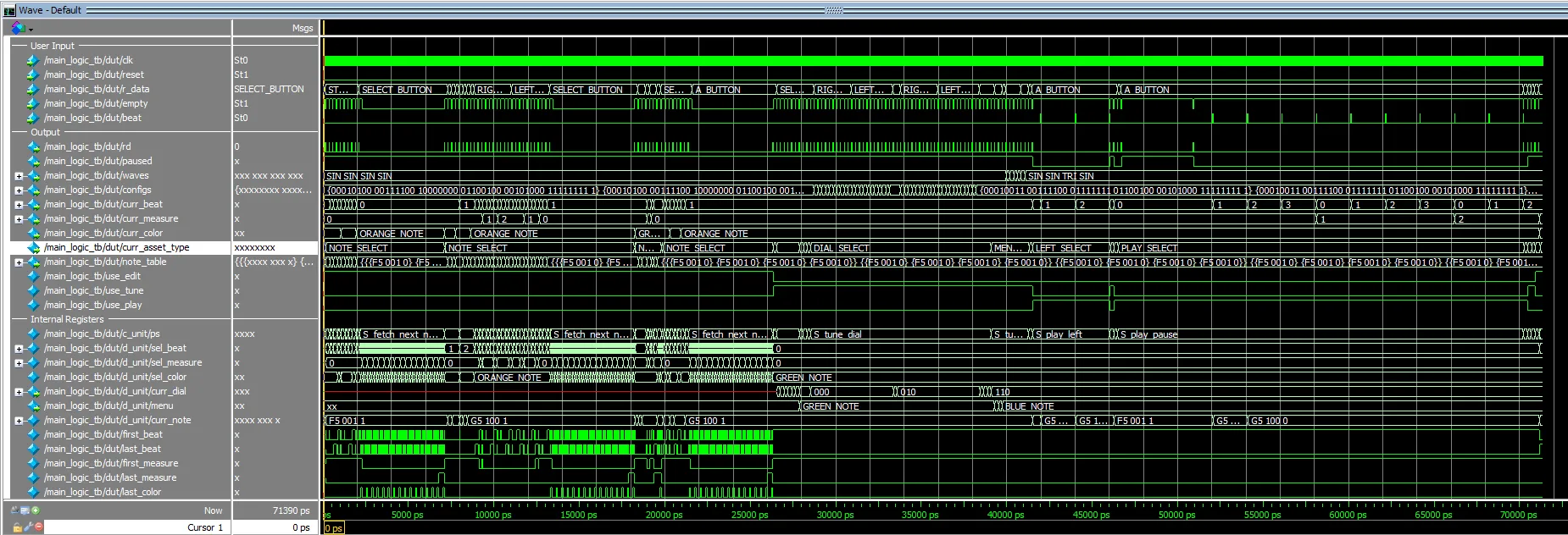 Figure 38:Overall waveform of the input buffer testbench (which also tests the serial driver).
# [130] --- Test Case 1: Navigating to Edit Note ---
# [7310] --- SELECTED NOTE ---
#     Mode:     NOTE_SELECT
#     Location: Measure 0, Beat 0
#     Color:    GREEN_NOTE
#     Paused:   1
# ------------------
#     Measure 0, Beat 0 | Color: GREEN_NOTE | Pitch: F5   | Length: 1
#     Measure 0, Beat 1 | Color: GREEN_NOTE | Pitch: F5   | Length: 1
#     Measure 0, Beat 2 | Color: GREEN_NOTE | Pitch: F5   | Length: 1
#     Measure 0, Beat 3 | Color: GREEN_NOTE | Pitch: F5   | Length: 1
#     Measure 0, Beat 0 | Color: BLUE_NOTE  | Pitch: F5   | Length: 1
#     Measure 0, Beat 1 | Color: BLUE_NOTE  | Pitch: F5   | Length: 1
#     Measure 0, Beat 2 | Color: BLUE_NOTE  | Pitch: F5   | Length: 1
#     Measure 0, Beat 3 | Color: BLUE_NOTE  | Pitch: F5   | Length: 1
#     Measure 0, Beat 0 | Color: ORANGE_NOTE | Pitch: F5   | Length: 1
#     Total Active Notes: 9
# --------------------------------
#
# [7310] --- Test Case 2: Pitch, Length, Color Adjustments ---
# [7530] --- SELECTED NOTE ---
#     Mode:     NOTE_SELECT
#     Location: Measure 0, Beat 0
#     Color:    GREEN_NOTE
#     Paused:   1
# ------------------
#     Measure 0, Beat 0 | Color: GREEN_NOTE | Pitch: G5   | Length: 1
#     Measure 0, Beat 1 | Color: GREEN_NOTE | Pitch: F5   | Length: 1
#     Measure 0, Beat 2 | Color: GREEN_NOTE | Pitch: F5   | Length: 1
#     Measure 0, Beat 3 | Color: GREEN_NOTE | Pitch: F5   | Length: 1
#     Measure 0, Beat 0 | Color: BLUE_NOTE  | Pitch: F5   | Length: 1
#     Measure 0, Beat 1 | Color: BLUE_NOTE  | Pitch: F5   | Length: 1
#     Measure 0, Beat 2 | Color: BLUE_NOTE  | Pitch: F5   | Length: 1
#     Measure 0, Beat 3 | Color: BLUE_NOTE  | Pitch: F5   | Length: 1
#     Measure 0, Beat 0 | Color: ORANGE_NOTE | Pitch: F5   | Length: 1
#     Total Active Notes: 9
# --------------------------------
# [7750] --- SELECTED NOTE ---
#     Mode:     NOTE_SELECT
#     Location: Measure 0, Beat 0
#     Color:    GREEN_NOTE
#     Paused:   1
# ------------------
#     Measure 0, Beat 0 | Color: GREEN_NOTE | Pitch: G5   | Length: 4
#     Measure 0, Beat 1 | Color: GREEN_NOTE | Pitch: F5   | Length: 1
#     Measure 0, Beat 2 | Color: GREEN_NOTE | Pitch: F5   | Length: 1
#     Measure 0, Beat 3 | Color: GREEN_NOTE | Pitch: F5   | Length: 1
#     Measure 0, Beat 0 | Color: BLUE_NOTE  | Pitch: F5   | Length: 1
#     Measure 0, Beat 1 | Color: BLUE_NOTE  | Pitch: F5   | Length: 1
#     Measure 0, Beat 2 | Color: BLUE_NOTE  | Pitch: F5   | Length: 1
#     Measure 0, Beat 3 | Color: BLUE_NOTE  | Pitch: F5   | Length: 1
#     Measure 0, Beat 0 | Color: ORANGE_NOTE | Pitch: F5   | Length: 1
#     Total Active Notes: 9
# --------------------------------
# [7970] --- SELECTED NOTE ---
#     Mode:     NOTE_SELECT
#     Location: Measure 0, Beat 0
#     Color:    BLUE_NOTE
#     Paused:   1
# ------------------
#     Measure 0, Beat 1 | Color: GREEN_NOTE | Pitch: F5   | Length: 1
#     Measure 0, Beat 2 | Color: GREEN_NOTE | Pitch: F5   | Length: 1
#     Measure 0, Beat 3 | Color: GREEN_NOTE | Pitch: F5   | Length: 1
#     Measure 0, Beat 0 | Color: BLUE_NOTE  | Pitch: G5   | Length: 4
#     Measure 0, Beat 1 | Color: BLUE_NOTE  | Pitch: F5   | Length: 1
#     Measure 0, Beat 2 | Color: BLUE_NOTE  | Pitch: F5   | Length: 1
#     Measure 0, Beat 3 | Color: BLUE_NOTE  | Pitch: F5   | Length: 1
#     Measure 0, Beat 0 | Color: ORANGE_NOTE | Pitch: F5   | Length: 1
#     Total Active Notes: 8
# --------------------------------
# [8410] --- SELECTED NOTE ---
#     Mode:     NOTE_SELECT
#     Location: Measure 0, Beat 1
#     Color:    BLUE_NOTE
#     Paused:   1
# ------------------
#     Measure 0, Beat 1 | Color: GREEN_NOTE | Pitch: F5   | Length: 1
#     Measure 0, Beat 2 | Color: GREEN_NOTE | Pitch: F5   | Length: 1
#     Measure 0, Beat 3 | Color: GREEN_NOTE | Pitch: F5   | Length: 1
#     Measure 0, Beat 0 | Color: BLUE_NOTE  | Pitch: G5   | Length: 4
#     Measure 0, Beat 1 | Color: BLUE_NOTE  | Pitch: G5   | Length: 1
#     Measure 0, Beat 2 | Color: BLUE_NOTE  | Pitch: F5   | Length: 1
#     Measure 0, Beat 3 | Color: BLUE_NOTE  | Pitch: F5   | Length: 1
#     Measure 0, Beat 0 | Color: ORANGE_NOTE | Pitch: F5   | Length: 1
#     Total Active Notes: 8
# --------------------------------
# [8630] --- SELECTED NOTE ---
#     Mode:     NOTE_SELECT
#     Location: Measure 0, Beat 1
#     Color:    BLUE_NOTE
#     Paused:   1
# ------------------
#     Measure 0, Beat 1 | Color: GREEN_NOTE | Pitch: F5   | Length: 1
#     Measure 0, Beat 2 | Color: GREEN_NOTE | Pitch: F5   | Length: 1
#     Measure 0, Beat 3 | Color: GREEN_NOTE | Pitch: F5   | Length: 1
#     Measure 0, Beat 0 | Color: BLUE_NOTE  | Pitch: G5   | Length: 4
#     Measure 0, Beat 1 | Color: BLUE_NOTE  | Pitch: G5   | Length: 4
#     Measure 0, Beat 2 | Color: BLUE_NOTE  | Pitch: F5   | Length: 1
#     Measure 0, Beat 3 | Color: BLUE_NOTE  | Pitch: F5   | Length: 1
#     Measure 0, Beat 0 | Color: ORANGE_NOTE | Pitch: F5   | Length: 1
#     Total Active Notes: 8
# --------------------------------
# [8850] --- SELECTED NOTE ---
#     Mode:     NOTE_SELECT
#     Location: Measure 0, Beat 1
#     Color:    ORANGE_NOTE
#     Paused:   1
# ------------------
#     Measure 0, Beat 1 | Color: GREEN_NOTE | Pitch: F5   | Length: 1
#     Measure 0, Beat 2 | Color: GREEN_NOTE | Pitch: F5   | Length: 1
#     Measure 0, Beat 3 | Color: GREEN_NOTE | Pitch: F5   | Length: 1
#     Measure 0, Beat 0 | Color: BLUE_NOTE  | Pitch: G5   | Length: 4
#     Measure 0, Beat 2 | Color: BLUE_NOTE  | Pitch: F5   | Length: 1
#     Measure 0, Beat 3 | Color: BLUE_NOTE  | Pitch: F5   | Length: 1
#     Measure 0, Beat 0 | Color: ORANGE_NOTE | Pitch: F5   | Length: 1
#     Measure 0, Beat 1 | Color: ORANGE_NOTE | Pitch: G5   | Length: 4
#     Total Active Notes: 8
# --------------------------------
# [8850] Note modifications completed.
#
# [8850] --- Test Case 3: Shifting Note Right and Left ---
# [11050] --- SELECTED NOTE ---
#     Mode:     NOTE_SELECT
#     Location: Measure 2, Beat 3
#     Color:    ORANGE_NOTE
#     Paused:   1
# ------------------
#     Measure 0, Beat 1 | Color: GREEN_NOTE | Pitch: F5   | Length: 1
#     Measure 0, Beat 2 | Color: GREEN_NOTE | Pitch: F5   | Length: 1
#     Measure 0, Beat 3 | Color: GREEN_NOTE | Pitch: F5   | Length: 1
#     Measure 0, Beat 0 | Color: BLUE_NOTE  | Pitch: G5   | Length: 4
#     Measure 0, Beat 2 | Color: BLUE_NOTE  | Pitch: F5   | Length: 1
#     Measure 0, Beat 3 | Color: BLUE_NOTE  | Pitch: F5   | Length: 1
#     Measure 0, Beat 0 | Color: ORANGE_NOTE | Pitch: F5   | Length: 1
#     Measure 2, Beat 3 | Color: ORANGE_NOTE | Pitch: G5   | Length: 4
#     Total Active Notes: 8
# --------------------------------
# [13250] --- SELECTED NOTE ---
#     Mode:     NOTE_SELECT
#     Location: Measure 0, Beat 1
#     Color:    ORANGE_NOTE
#     Paused:   1
# ------------------
#     Measure 0, Beat 1 | Color: GREEN_NOTE | Pitch: F5   | Length: 1
#     Measure 0, Beat 2 | Color: GREEN_NOTE | Pitch: F5   | Length: 1
#     Measure 0, Beat 3 | Color: GREEN_NOTE | Pitch: F5   | Length: 1
#     Measure 0, Beat 0 | Color: BLUE_NOTE  | Pitch: G5   | Length: 4
#     Measure 0, Beat 2 | Color: BLUE_NOTE  | Pitch: F5   | Length: 1
#     Measure 0, Beat 3 | Color: BLUE_NOTE  | Pitch: F5   | Length: 1
#     Measure 0, Beat 0 | Color: ORANGE_NOTE | Pitch: F5   | Length: 1
#     Measure 0, Beat 1 | Color: ORANGE_NOTE | Pitch: G5   | Length: 4
#     Total Active Notes: 8
# --------------------------------
# [19090] --- SELECTED NOTE ---
#     Mode:     NOTE_SELECT
#     Location: Measure 1, Beat 0
#     Color:    GREEN_NOTE
#     Paused:   1
# ------------------
#     Measure 0, Beat 2 | Color: GREEN_NOTE | Pitch: F5   | Length: 1
#     Measure 0, Beat 3 | Color: GREEN_NOTE | Pitch: F5   | Length: 1
#     Measure 1, Beat 0 | Color: GREEN_NOTE | Pitch: F5   | Length: 2
#     Measure 0, Beat 0 | Color: BLUE_NOTE  | Pitch: G5   | Length: 4
#     Measure 0, Beat 2 | Color: BLUE_NOTE  | Pitch: F5   | Length: 1
#     Measure 0, Beat 3 | Color: BLUE_NOTE  | Pitch: F5   | Length: 1
#     Measure 0, Beat 0 | Color: ORANGE_NOTE | Pitch: F5   | Length: 1
#     Measure 0, Beat 1 | Color: ORANGE_NOTE | Pitch: G5   | Length: 4
#     Total Active Notes: 8
# --------------------------------
# [19530] --- SELECTED NOTE ---
#     Mode:     NOTE_SELECT
#     Location: Measure 0, Beat 0
#     Color:    GREEN_NOTE
#     Paused:   1
# ------------------
#     Measure 0, Beat 0 | Color: GREEN_NOTE | Pitch: F5   | Length: 2
#     Measure 0, Beat 2 | Color: GREEN_NOTE | Pitch: F5   | Length: 1
#     Measure 0, Beat 3 | Color: GREEN_NOTE | Pitch: F5   | Length: 1
#     Measure 0, Beat 0 | Color: BLUE_NOTE  | Pitch: G5   | Length: 4
#     Measure 0, Beat 2 | Color: BLUE_NOTE  | Pitch: F5   | Length: 1
#     Measure 0, Beat 3 | Color: BLUE_NOTE  | Pitch: F5   | Length: 1
#     Measure 0, Beat 0 | Color: ORANGE_NOTE | Pitch: F5   | Length: 1
#     Measure 0, Beat 1 | Color: ORANGE_NOTE | Pitch: G5   | Length: 4
#     Total Active Notes: 8
# --------------------------------
# [19530] Notes shifted.
#
# [19530] --- Test Case 4: Deleting Current Note ---
# [19750] --- SELECTED NOTE ---
#     Mode:     NOTE_SELECT
#     Location: Measure 0, Beat 0
#     Color:    GREEN_NOTE
#     Paused:   1
# ------------------
#     Measure 0, Beat 2 | Color: GREEN_NOTE | Pitch: F5   | Length: 1
#     Measure 0, Beat 3 | Color: GREEN_NOTE | Pitch: F5   | Length: 1
#     Measure 0, Beat 0 | Color: BLUE_NOTE  | Pitch: G5   | Length: 4
#     Measure 0, Beat 2 | Color: BLUE_NOTE  | Pitch: F5   | Length: 1
#     Measure 0, Beat 3 | Color: BLUE_NOTE  | Pitch: F5   | Length: 1
#     Measure 0, Beat 0 | Color: ORANGE_NOTE | Pitch: F5   | Length: 1
#     Measure 0, Beat 1 | Color: ORANGE_NOTE | Pitch: G5   | Length: 4
#     Total Active Notes: 7
# --------------------------------
#
Figure 39:Transcript of what sorts of outputs are being read from the testbench.
In this testbench, we verify the main_logic module, confirming the FSM correctly interprets user input from the FIFO and safely manipulates the complex 3D composition memory array.
From 130 ps to 7310 ps (Test Case 1), we test basic UI navigation. The FSM successfully routes START_BUTTON presses, automatically finding the next available empty memory slots and generating 9 active placeholder notes initialized safely at F5.
During Test Case 2 (7530 ps to 8850 ps), we test data modification. Utilizing the UP_BUTTON and DOWN_BUTTON, the datapath correctly overwrites the selected note’s pitch (shifting from F5 to G5) and modifies its length (from 1 to 4). Furthermore, pressing A_BUTTON successfully transfers the note data to the BLUE_NOTE layer while erasing it from the GREEN_NOTE layer, proving the read-modify-write cycle works seamlessly across the Z-axis of the memory array.
Finally, in Test Case 3 (11050 ps to 19530 ps) and Test Case 4 (19750 ps), we test temporal shifting and deletion. By holding the RIGHT_BUTTON, the orange whole note is perfectly relocated from Measure 0, Beat 1 to Measure 2, Beat 3 without data corruption. When the B_BUTTON is pressed at 19750 ps, the datapath correctly drops the is_en flag of the active green note, instantly reducing the total active note count from 8 to 7.
Flow Summary
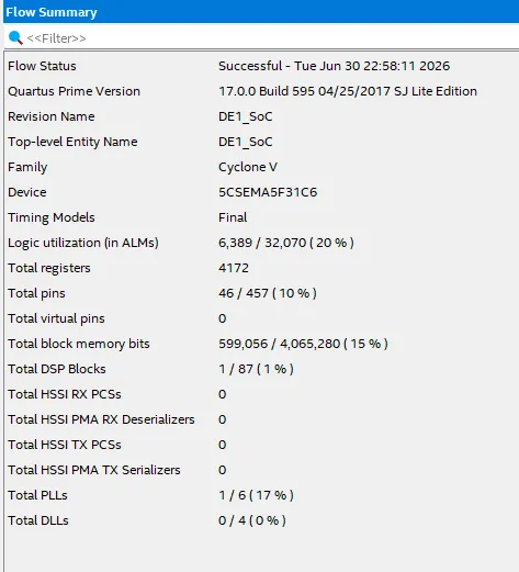 Figure 40:The ModelSim Flow Summary of the compilation of the DE1_SoC module.
Experience Report
Working on this project gave me both the best and worst experiences of all the CSE coursework.
I think the worst part was feature creep: I was extremely ambitious with my project, and I feel like I wrote a lot of code (including many Python files to create some of the necessary files for the FPGA). As is clear from the breakdown of my time spent on this project, there were many different ASMDs to write and design, and I do not believe that was on my mind when I first started this project in the project proposal. To avoid issues like this in the future, I think I ought to make a more “simple” version for the initial proposal, and add stretch goals for myself that can be optionally included.
However, it was this ambition that made the project as fun as it was. In this project alone, I contributed a sizable amount of my time during finals week. From writing the ASMDs to writing testbenches, it was great watching my code output exactly what I wanted, and eventually watching it output to the LabsLand VGA viewer and listening back to the recording during the play screen.
Some of the roadblocks were related to the planning phase. While it was smooth sailing after the planning, I really struggled to conceptualize the design (as indicated by the time I spent specifically on it). Many aspects of the design underwent multiple revisions. Take, for example, the “main logic” ASMD. In the proposal, I started with a main logic board that would communicate directly with the rendering engine and audio generator. However, there were nearly 50 different states! Upon this realization, I decided to break it into multiple ASMDs (the drawers and the main logic) and have simple status signals sent from the main logic to the drawers!
I believe that my research on things like typedefs and enums allowed me to craft something easy to code and understand, making the coding and debugging stages relatively straightforward. Similarly, my work in my clubs allowed me to view the project more holistically and make sound design decisions that made my life easier down the road. Reflecting on this, however, I believe I should have spent less time on the design, as it delayed my project and led me to submit later than expected.
In the end, this lab has made me even more confident in my skills as a software engineer and my ability to design systems at a high level, and has allowed me to exercise and hone the new abilities I’ve acquired from CSE 369 and 371 (potentially motivating me to buy a cheaper FPGA for home use).
This lab took approximately 93 hours, broken down as follows:
- Reading, Brainstorming, and Planning (i.e., Project Proposal)– 5 hours
- Design & ASMD Conversion – 40 hours
- Coding – 20 hours
- Testing & Simulation – 10 hours
- Debugging – 6 hours
- Producing writeup and video – 12 hours